
Quick Answer: A reflow soldering profile is a strictly controlled thermal recipe that dictates the exact temperature and time a printed circuit board experiences inside an oven, typically ramping from 25°C to a peak of 245°C over 4 to 5 minutes. Proper optimization eliminates up to 90% of factory assembly defects like tombstoning and voiding by keeping the temperature difference (ΔT) across the board strictly under 10°C.
Key takeaways:
- The preheat zone must ramp exactly 1.0°C to 3.0°C per second to prevent thermal shock and component cracking.
- The soak zone holds the board between 150°C and 200°C for 60 to 120 seconds, allowing heavy copper planes to catch up to smaller components.
- Lead-free SAC305 solder requires a peak temperature of 240°C to 250°C, which is 20-30°C above its 217°C liquidus melting point.
- Time Above Liquidus (TAL) must remain between 45 and 90 seconds; exceeding this creates brittle intermetallic joints, while falling short traps flux gas and causes >25% BGA voiding.
Table of Contents
- 1. What Is a Reflow Soldering Profile and Why Does It Matter?
- 2. What Are the Four Zones of a Reflow Profile?
- 3. How Do Lead-Free and Leaded Reflow Profiles Differ?
- 4. What Defects Does a Bad Reflow Profile Cause?
- 5. How Do You Set the Right Preheat Ramp Rate?
- 6. What Soak Time and Temperature Prevent Tombstoning?
- 7. How Do You Optimize Peak Temperature and Time Above Liquidus?
- 8. How Should You Profile a Mixed-Component Board?
- 9. What Tools Do You Need for Thermal Profiling?
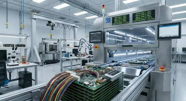
Watching expensive processors fail functional testing because of invisible solder joint cracks frustrates every hardware team. You design a perfect schematic, but when the factory guesses the oven temperatures, trapped gas forms voids under your BGAs and tiny resistors stand up on one end. Mastering the reflow soldering profile eliminates these physical layout failures before mass production begins. At QueenEMS, deploying 10-zone nitrogen reflow ovens and strictly controlling thermal profiles allows us to maintain a 99.7% first-pass yield rate, dropping defect rework costs to zero for our clients.
1. What Is a Reflow Soldering Profile and Why Does It Matter?
A reflow soldering profile is a strictly controlled thermal graph dictating the exact temperature and exposure time a printed circuit board experiences inside an automated oven, typically running a 4 to 5-minute cycle peaking at 245°C. Following the IPC-7530 standard, engineers use this profile to physically control how fast solder paste heats up, melts, and cools down, preventing physical damage to sensitive silicon chips.
The profile directly controls the heating rates to stop thermal shock, keeping the delta T (ΔT)—the temperature difference between the hottest and coldest components on the board—under exactly 10°C. If a factory runs your boards through a generic profile without attaching thermocouples, the heavy copper ground planes will stay cold while the small 0201 capacitors overheat and burn.
- The Heating Phase: Drives off volatile solvents in the flux before the paste actually melts.
- The Melting Phase: Reaches 217°C (for lead-free) to physically bond the metal pads.
- The Cooling Phase: Drops the temperature rapidly to solidify the joint without making it brittle.
Bottom line: Treat the thermal profile as the physical blueprint for your solder joints; running blind temperatures leads directly to a 30% field failure rate.
2. What Are the Four Zones of a Reflow Profile?
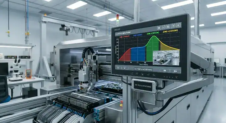
A standard reflow profile consists of four distinct operational zones: preheat (ramping 1-3°C/sec), soak (holding 150-200°C for 60-120s), reflow (peaking above 217°C for 45-90s), and cooling (dropping -2 to -4°C/sec). Each zone serves an exact chemical and thermodynamic purpose based on the J-STD-020 classification standards.
When you review a factory’s oven graph, you must see these four distinct phases. The preheat zone safely raises the ambient temperature. The soak zone acts as a thermal equalizer, giving large components time to catch up to smaller ones. The reflow zone (also called Time Above Liquidus, or TAL) actually forms the electromechanical bond. Finally, the cooling zone freezes the metal quickly to create a fine-grain, reliable structure.
| Zone Name | Temp Range (Lead-Free) | Duration / Ramp Rate | Core Purpose |
|---|---|---|---|
| 1. Preheat | 25°C to 150°C | 1.0 – 3.0°C per second | Safely evaporate paste solvents |
| 2. Soak | 150°C to 200°C | 60 – 120 seconds | Equalize thermal mass across the board |
| 3. Reflow (TAL) | 217°C to 245°C | 45 – 90 seconds | Melt solder and form intermetallic bond |
| 4. Cooling | 245°C down to 25°C | -2.0 to -4.0°C per second | Solidify the joint quickly to prevent brittleness |
Comparison Anchor: If you are running standard prototype boards, a basic 4-zone profile handles the job; if you are running dense, high-volume aerospace boards, demand a custom profile utilizing a 10-zone or 12-zone oven for hyper-accurate temperature stepping.
Bottom line: Never accept an oven profile that lacks a distinct soak zone, as skipping it guarantees extreme temperature mismatches across your circuit board.
3. How Do Lead-Free and Leaded Reflow Profiles Differ?
Lead-free reflow profiles require a significantly higher peak temperature of 240°C to 250°C to melt standard SAC305 solder (which has a 217°C liquidus point), whereas traditional tin-lead solder melts at just 183°C and peaks safely around 215°C. This massive 34°C difference in melting points completely changes the margin of error available to process engineers.
Because lead-free solder demands such high heat, the physical processing window shrinks drastically. You must push the oven hot enough to melt the SAC305 alloy, but keeping it under the 260°C maximum thermal limit of most plastic component packages leaves you with a tiny 10°C to 15°C safety margin.
| Feature | Lead-Free (SAC305) | Traditional Leaded (Sn63Pb37) | Impact on Manufacturing |
|---|---|---|---|
| Melting Point | 217°C | 183°C | Requires more aggressive oven heating |
| Target Peak Temp | 240°C – 250°C | 210°C – 215°C | Pushes components closer to physical damage limits |
| Time Above Liquidus | 45 – 90 seconds | 60 – 90 seconds | Tighter timing required to prevent thick intermetallics |
| Margin of Error | 10°C to 15°C | 30°C to 40°C | Demands extremely precise 10-zone oven control |
Comparison Anchor: If you build medical or aerospace devices exempt from RoHS, choose leaded profiles for a massive 40°C margin of error; if you build consumer electronics, you must choose lead-free and invest heavily in thermal profiling optimization.
Bottom line: Lead-free assembly removes almost all thermal safety margins, making automated data loggers mandatory to prevent destroying expensive microprocessors.
4. What Defects Does a Bad Reflow Profile Cause?
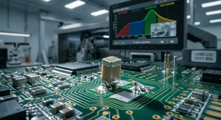
A bad reflow soldering profile directly causes up to 90% of thermal defects, including tombstoning when preheating exceeds 3°C/sec, excessive BGA voiding when soak times fall under 60 seconds, and solder bridging when cooling drops slower than -2°C/sec.
Many engineers running small quick turn PCB assembly batches frequently face severe tombstoning issues, especially on 0402 and 0201 passive components, and instantly blame the solder paste.
Here is the exact truth: tombstoning happens because the solder paste on one pad melts a fraction of a second before the other pad, creating an asymmetrical wetting force that literally pulls the resistor upright. If multiple 0402 components across different physical areas of the board are tombstoning, it is almost certainly a profile issue, not a paste issue. Your ramp rate is hitting the board too fast. The fix is lowering your preheat ramp rate down to 1.0-2.0°C/sec and extending the soak time to make the temperature perfectly uniform. Conversely, if tombstoning only happens in one specific corner, you likely have asymmetrical pad design or uneven paste deposits.
| Defect Type | Problem Zone | Root Cause Parameter | The Factory Fix |
|---|---|---|---|
| Tombstoning | Preheat / Soak | Ramp rate >3°C/s (heating too fast) | Drop ramp to 1.5°C/s, extend soak duration |
| BGA Voiding | Soak / Reflow | Soak too short, flux trapped inside | Extend soak to 100s to let volatiles escape |
| Solder Bridging | Reflow / Cooling | Peak temp too high, cooling too slow | Lower peak by 5°C, increase cooling to -3°C/s |
| Cold Joints | Reflow (TAL) | TAL under 40s or peak under 235°C | Increase peak temp and extend TAL to 60s |
Comparison Anchor: If you see tiny components standing upright, immediately flatten your preheat ramp rate; if you see dull, grainy solder joints, immediately raise your peak temperature.
Bottom line: Stop blaming the bare PCB or the stencil for tombstoning; immediately attach a thermocouple and lower your preheat ramp rate below 2.0°C per second.
5. How Do You Set the Right Preheat Ramp Rate?
The optimal preheat ramp rate must remain strictly between 1.0°C and 3.0°C per second to safely evaporate solder paste solvents without causing violent outgassing or physically cracking sensitive ceramic capacitors.
Pushing the board temperature too quickly causes the flux inside the solder paste to boil rapidly rather than evaporate smoothly. This boiling action creates micro-explosions that physically spit tiny solder balls across the green solder mask.
- Factory experience: A client submitted a dense IoT board and suffered a disastrous 12% failure rate due to cracked MLCC ceramic capacitors and massive solder balling.
- Our solution: We attached a DATAPAQ logger, discovered their previous CM used an aggressive 3.5°C/sec ramp, and immediately reprogrammed our oven to a gentle 1.5°C/sec rate.
- The result: The capacitor micro-cracking disappeared entirely, dropping the defect rate to 0.1% on the very next 500-unit production run.
Bottom line: Limit your initial oven ramp rate to a maximum of 2.0°C per second to protect ceramic capacitors from microscopic thermal stress fractures.
6. What Soak Time and Temperature Prevent Tombstoning?
To completely prevent tombstoning, the soak zone must hold the circuit board between 150°C and 200°C for exactly 60 to 120 seconds, allowing heavy copper planes to thermally equalize with tiny component pads.
During the soak phase, the flux activates and strips the oxidation off the copper pads. If this zone is too short (under 60 seconds), the thermal mass differences across the board remain massive. A tiny pad connected to a thin trace will hit 217°C and melt its solder instantly, while the adjacent pad connected to a massive ground plane remains stuck at 200°C. That timing mismatch generates the physical pull force that rips the component upright into a tombstone.
Consider this Before/After optimization:
- Bad Profile: Ramp 3.5°C/s → Soak 45 seconds → Tombstone defect rate: 8%
- Corrected Profile: Ramp 1.5°C/s → Soak 110 seconds → Tombstone defect rate: 0%
Bottom line: Extend your soak zone duration to at least 90 seconds to guarantee both ends of a passive component melt at the exact same millisecond.
7. How Do You Optimize Peak Temperature and Time Above Liquidus?
To optimize the reflow zone for lead-free SAC305, set the peak temperature strictly to 245°C (which is 28°C above the 217°C liquidus) and maintain the Time Above Liquidus (TAL) strictly between 45 and 90 seconds.
Engineers frequently panic when they X-ray a lead-free BGA and discover a voiding rate over 25%, immediately questioning whether they should spike the peak temperature or dramatically extend the TAL. Understand this trade-off: Voiding happens when flux outgassing gets trapped inside the molten solder ball. Raising the peak temperature (from 240°C to 250°C) lowers the physical viscosity of the liquid solder, making it easier for trapped gas bubbles to float out. However, pushing past 250°C risks melting plastic connectors. Extending the TAL (from 45s to 75s) simply gives the bubbles more time to escape. But leave the board liquid for over 90 seconds, and the copper-tin intermetallic layer grows too thick, creating an extremely brittle joint that snaps when dropped.
The most effective solution balances both. Set a moderate peak temperature of 245°C combined with a 60-75 second TAL, while simultaneously verifying the soak zone actively burned off the volatiles beforehand. Keep in mind, the IPC-A-610 standard sets the acceptable limit for BGA voiding at 25% of the total X-ray area.
Bottom line: Fix BGA voiding by targeting a 245°C peak and a 70-second TAL; pushing the board hotter than 250°C will permanently warp your PCB substrate.
8. How Should You Profile a Mixed-Component Board?
Profiling a mixed-component board requires extending the soak time by up to 30% to allow heavy power inductors to catch up thermally, rather than simply increasing the peak temperature and destroying the adjacent 0201 capacitors.
A massive engineering headache occurs when a board hosts a bulky power inductor with a heavy copper pad right next to microscopic passives. The large thermal mass component absorbs heat incredibly slowly, often lagging 20°C behind the rest of the board. If you lazily increase the oven’s peak temperature to force the heavy inductor to reach liquidus, the tiny 0201 capacitors will hit 265°C and sustain severe silicon damage.
The solution requires hardware capability: You cannot solve a mixed thermal mass board on a cheap 4-zone oven. You must use a multi-zone system (like QueenEMS’s 10-zone nitrogen ovens) to set different ramp rates.
- Factory experience: A customer’s complex telecom board showed massive ΔT spreads, with the primary processor failing to reflow completely.
- Our solution: We abandoned the generic profile, programmed zones 3 through 6 for a heavily extended soak time to allow thermal equalization, and used a moderate peak in zone 8.
- The result: We successfully closed the temperature gap, hitting a ΔT of under 8°C across the entire board, securing 100% perfect wetting on both the heavy inductors and the tiny capacitors.
Bottom line: Never raise the peak temperature to fix a cold solder joint on a heavy component; you must extend the soak duration to equalize the board first.
9. What Tools Do You Need for Thermal Profiling?
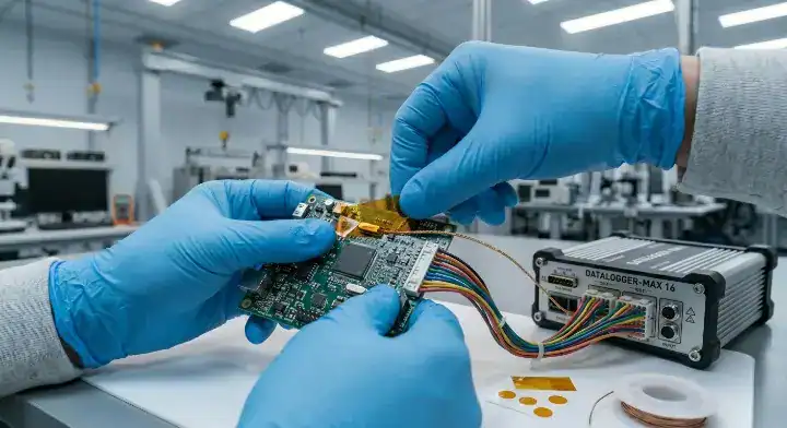
Accurate thermal profiling requires specialized equipment like KIC or DATAPAQ data loggers paired directly with 4 to 6 physical K-type thermocouples attached precisely to the hottest and coldest joints on the printed circuit board.
You cannot guess oven temperatures by looking at the machine’s external LED display. The air temperature inside the oven is drastically different from the physical board temperature at the pad level. To capture the real data, process engineers apply high-temperature epoxy to glue thermocouples directly onto a “golden board,” running this physical logger through the oven to capture a live thermal graph.
| Profiler Equipment | Thermocouple Count | Typical Price Range | Best Used For |
|---|---|---|---|
| Standard Data Logger | 3 to 4 channels | $1,500 – $3,000 | Simple consumer prototype boards |
| Advanced KIC System | 6 to 9 channels | $6,000 – $12,000 | Complex mixed-assembly BGAs |
| DATAPAQ Reflow Tracker | Up to 12 channels | $10,000+ | Aerospace and extreme high-mass boards |
| Virtual Profiling Software | N/A (Algorithm based) | Subscription | Predicting changes before physical runs |
Comparison Anchor: If you are prototyping a 2-layer board with basic passives, a standard 4-channel logger is perfectly adequate; if you are manufacturing 12-layer telecom boards with massive BGAs, demand your EMS uses a 9-channel KIC system to map every single thermal shadow.
Bottom line: A reliable EMS partner will willingly provide you with the raw thermocouple data graph proving your specific board stayed within the exact 10°C ΔT limit.
Gain Total Control Over Your SMT Yields
Guessing the exact temperature your board needs is a gamble that always ends in expensive rework. A bad profile hides micro-cracks, traps massive voids under expensive silicon, and forces your procurement team to order replacement chips out of pocket. You need an assembly partner who treats thermodynamic data as strict science, matching oven parameters to your exact SMT stencil and component mass.
At QueenEMS, we do not guess. Our engineering team attaches 6-point thermal loggers to your specific bare board layout, running dedicated test passes through our 10-zone nitrogen reflow ovens before mass production starts. By strictly controlling the Time Above Liquidus and holding the ΔT under 10°C, we completely eliminate tombstoning and BGA voiding.
Stop paying for generic oven settings that ruin your silicon. Contact us today to discuss your specific high-density board requirements, and let our thermal profiling experts engineer a zero-defect assembly process for your next launch.
Written by the QueenEMS Engineering Team
FAQ
1. Does a lead-free profile take longer than a traditional leaded profile? Yes, a lead-free SAC305 profile generally takes 30 to 45 seconds longer to complete. Because the melting point is 34°C higher, the board requires an extended soak phase to safely ramp the temperature up without thermally shocking the internal layers of the FR4 substrate. Pushing it faster guarantees component cracking.
2. Can I use a generic oven profile if my board only has standard SMD components? It depends entirely on your copper plane density. Even if your components are standard, a board with a massive 2oz internal copper ground plane acts like a giant heat sink and requires a heavily modified soak zone compared to a simple 2-layer signal board. Always demand a custom profile run using an actual thermocouple logger.
3. Will adding nitrogen gas to the reflow oven fix a bad temperature profile? No, nitrogen only displaces oxygen to prevent metal oxidation and widen the wetting process window. It will absolutely not fix the aggressive thermal shock caused by ramping the heat up at 4°C per second. You must fix the core temperature timings first, then add nitrogen to elevate the final joint quality.
Upload your files today · Free DFM check before production · Ship worldwide
Get your PCB prototypes in as fast as 24 hours. We handle FR4, Rogers, and Flex up to 60 layers — free prototypes for 2–4 layer boards, no minimum order.
Just upload your Gerber + BOM — we source every part, assemble, and inspect (AOI + X‑Ray) so you don't have to chase suppliers. Boards ship in as fast as 24 hours.