
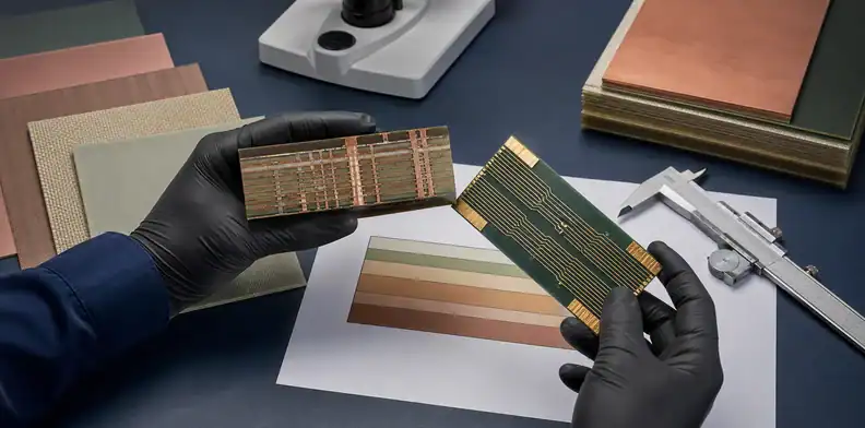
Quick Answer: IT-150DA PCB material is ITEQ’s high-Tg, lead-free, very-low-loss laminate and prepreg system. Its current datasheet lists Tg at 180°C by DSC, Td at 370°C at 5% weight loss, and typical Dk/Df of 3.64/0.0065 at 10 GHz and 50% resin content—but those catalog values are screening inputs, not a finished-channel guarantee.
Key takeaways: – The model number does not state the material’s Tg; the current official Tg is 180°C. – “Lead Free” does not prove compliance with every restricted-substance rule. – Compare Dk and Df only with their frequency, resin content, and test method attached. – Approve the actual stackup, process, assembly profile, and test plan—not a laminate name alone.
IT-150DA PCB material is worth evaluating when a multilayer board needs both lead-free thermal margin and lower dielectric loss than a conventional FR-4 construction can provide. The difficult part is not finding a short property table; it is deciding whether those values apply to your glass style, resin content, copper, geometry, and channel.
To compare laminate families, electrical behavior, fabrication limits, and sourcing trade-offs in one place, use the complete PCB materials guide.
Table of Contents
- What Is IT-150DA PCB Material—and What Is It Not?
- Which IT-150DA Datasheet Values Matter Most?
- What Does Lead Free Prove—and What Does It Not?
- How Does IT-150DA Compare with FR408HR?
- Where Does It Sit Beside I-Speed and IT-968?
- Which Designs Fit IT-150DA PCB Material?
- When Does a Hybrid Stackup Make Engineering Sense?
- What Fabrication Controls Should You Qualify?
- When Should You Evaluate a Lower-Loss Material?
- What Belongs in an IT-150DA PCB Material RFQ?
What Is IT-150DA PCB Material—and What Is It Not?
IT-150DA is an ITEQ advanced multifunctional epoxy laminate and prepreg system. The current manufacturer datasheet classifies it as “High Tg / Lead Free / Very Low Loss,” identifies the laminate as IT-150DATC and the prepreg as IT-150DABS, and gives it an ANSI type of FR-4.0.
The first naming trap is simple: 150 is not the published glass-transition temperature. ITEQ reports a Tg of 180°C by differential scanning calorimetry (DSC), so the model number and the measured property must stay separate in specifications.
The second trap is assuming that every desirable compliance attribute travels together. “Lead Free” is the manufacturer’s stated classification, but it does not establish every restricted-substance requirement. Procurement should request a current grade-specific declaration for each required environmental limit instead of inferring compliance from the name, FR-4 classification, or UL flammability rating.
For a material callout, specify the exact identifiers and datasheet revision. The current datasheet lists IPC-4101 /98, /99, /101, and /126, plus IPC-4103 /240 and /540; those references do not replace a construction drawing or project limits.
Which IT-150DA Datasheet Values Matter Most?
The useful IT-150DA values are the ones tied to a test method and design decision. Tg helps classify the resin system; Td, T260, T288, and z-axis expansion help screen thermal robustness; Dk and Df support early electrical modeling. None of them alone approves a finished board.
| Property | Current published value | Condition and interpretation |
|---|---|---|
| Tg | 180°C | DSC, IPC-TM-650 2.4.25; material transition, not a reflow limit |
| Td | 370°C | TGA at 5% weight loss, IPC-TM-650 2.4.24.6 |
| T260 / T288 | >60 / >30 min | Lower-bound values under IPC-TM-650 2.4.24.1 |
| Dk / Df at 10 GHz | 3.64 / 0.0065 | Typical, 50% resin content, IPC-TM-650 2.5.5.13 |
| Z-axis expansion | 2.6% | 50–260°C, IPC-TM-650 2.4.24 |
| Moisture absorption | 0.10% maximum | IPC-TM-650 2.6.2.1 |
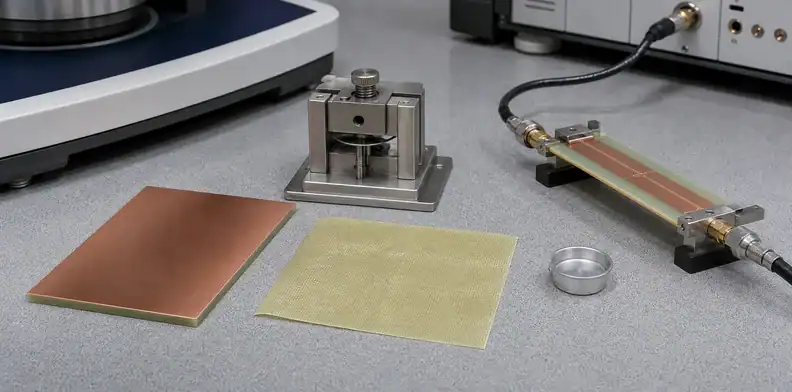
The electrical table also shows frequency dependence. At 1, 2, 5, and 10 GHz, the typical Dk values are 3.73, 3.71, 3.69, and 3.64; the typical Df values are 0.0052, 0.0053, 0.0057, and 0.0065. All are stated at 50% resin content under the same ITEQ method. This is more informative than one headline number, but it still does not capture the exact glass weave, pressed resin content, copper roughness, or conductor geometry in your board.
Treat >30 minutes at T288 correctly: it is a laminate test result, not permission for a fixed number of reflow cycles. The actual assembly risk also depends on peak temperature, time above liquidus, moisture conditioning, board thickness, via geometry, copper distribution, rework, and the fabricator’s process. A release decision should combine the material data with a representative assembly profile and board-level evidence.
What Does Lead Free Prove—and What Does It Not?
ITEQ’s “Lead Free” label positions IT-150DA for lead-free assembly conditions; it does not certify every finished PCB for every profile. It also does not establish other environmental limits, automotive qualification, or signal performance.
Several terms answer different questions:
- Lead-free classification: the laminate is positioned for lead-free processing, subject to the actual board and assembly qualification.
- UL 94 V-0: the datasheet reports a flammability classification; it is not a complete substance declaration.
- FR-4.0 and IPC slash sheets: these describe material categories and requirements, not a complete customer approval.
- CTI class 3: the published comparative tracking index range is 175–249 V; it should not be turned into an operating-voltage rule without the applicable safety design standard.
If a customer imposes a separate substance restriction, ask for a current declaration tied to IT-150DATC and IT-150DABS, the relevant test standard, measured limits, manufacturing site, and revision. If that evidence is unavailable, select a grade whose current documentation explicitly satisfies the requirement. A corporate environmental statement or a declaration for another ITEQ family is not grade-specific proof.
The laminate may be electrically and thermally suitable yet fail a customer’s restricted-substance requirement, or satisfy the paperwork but fail the channel or via target. Keep those approvals separate.
How Does IT-150DA Compare with FR408HR?
IT-150DA and FR408HR belong on the same early shortlist when a design needs a lead-free multilayer laminate with improved electrical performance, but their published numbers are not a clean head-to-head test. ITEQ and Isola use different Dk/Df methods in the current documents, so the table below is orientation rather than a loss ranking.
| Published property | IT-150DA | FR408HR | What the difference means |
|---|---|---|---|
| Tg by DSC | 180°C | 190°C | A higher Tg label does not by itself select the safer board |
| Td at 5% weight loss | 370°C | 360°C | Useful thermal screening under similar definitions |
| Dk at 10 GHz | 3.64 | 3.65 | Methods differ; do not infer identical impedance |
| Df at 10 GHz | 0.0065 | 0.0095 | IT-150DA has the lower published typical value, not proven lower channel loss |
| IPC-4101 references | /98, /99, /101, /126 | /98, /99, /101, /126 | Shared slash sheets do not make the grades drop-in equivalents |
IT-150DA’s 10 GHz figures are typical values at 50% resin content under IPC-TM-650 2.5.5.13. FR408HR’s current sheet uses the Bereskin stripline method at 10 GHz. Because method, test coupon, construction, and resin content affect the result, subtracting the two Df values or converting the gap into a percentage loss improvement would create false precision.
Start with the channel and assembly requirements, then request buildable constructions from both suppliers. Compare construction-specific design Dk, modeled insertion loss, copper profile, available cores and prepregs, impedance geometry, thermal data, and qualification evidence. QueenEMS’ FR408HR hybrid-stackup analysis provides further context for that material.
Where Does It Sit Beside I-Speed and IT-968?
IT-150DA sits near I-Speed in published 10 GHz Dk/Df, while ITEQ positions IT-968 as a lower-loss option on its product map. That statement is useful for portfolio orientation only; it is not proof that one material will meet a specific channel and another will fail it.
I-Speed’s official datasheet reports Tg 180°C by DSC, Td 360°C at 5% weight loss, T288 above 60 minutes, and Dk/Df of 3.63/0.0060 at 10 GHz by Bereskin stripline. IT-150DA reports 3.64/0.0065 at 10 GHz, 50% resin content, under IPC-TM-650 2.5.5.13. The close headline numbers justify a deeper comparison, not a claim of electrical equivalence. The I-Speed low-loss laminate profile is a useful next read when that grade is on the approved-material list.
ITEQ’s roadmap shows IT-968 at Dk 3.14 and Df 0.0039, but the roadmap groups IT-968 values at 70% resin content and IT-150DA values at 50%. It also does not expose every test detail in the product-map view. Put IT-968 on the evaluation list when the loss budget indicates that IT-150DA lacks margin, then obtain the current grade datasheet, construction data, and modeled or measured insertion loss.
Which Designs Fit IT-150DA PCB Material?
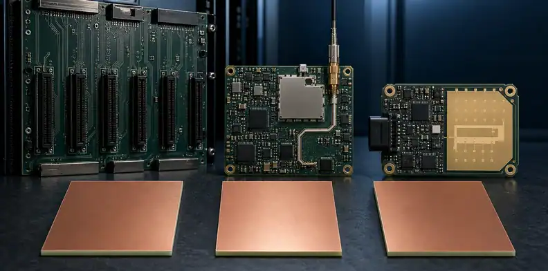
IT-150DA is a plausible candidate for loss-sensitive multilayer designs in the application categories ITEQ actually lists: servers, storage systems, switches, backplanes, telecom base stations, radio-frequency equipment, and automotive radar. The qualification still matters because the product page does not approve every architecture, data rate, layer count, or automotive environment.
For high-speed digital work, start with the longest and most loss-sensitive channels. Allocate the total insertion-loss budget across dielectric loss, conductor loss, vias, connectors, packages, and margin. IT-150DA deserves further evaluation if a conventional FR-4 construction consumes too much dielectric-loss budget while the proposed IT-150DA build remains manufacturable and commercially acceptable.
For telecom or 5G equipment, separate the RF path from control, power, and digital regions. The manufacturer’s telecom-base-station and RF categories make the material relevant, but they do not prove a particular 5G frequency band or radio architecture. QueenEMS’ 5G base-station material selection covers the broader application decision; the board still needs a frequency- and construction-specific model.
Automotive radar is a manufacturer-listed category, not an automatic automotive qualification. Define temperature, humidity, cycling, vibration, reliability, production sites, and traceability; do not extend the radar listing to every ECU or infotainment board.
For dense interconnects, the material decision and the HDI process decision must meet. The current IT-150DA datasheet does not make a blanket HDI compatibility claim, so sequential lamination, microvia reliability, resin flow, and desmear need construction-level approval. The HDI PCB fabrication requirements provide a useful discussion framework without replacing material qualification.
When Does a Hybrid Stackup Make Engineering Sense?
A hybrid stackup makes sense when only a defined subset of layers or channels requires IT-150DA’s loss characteristics and the fabricator can qualify the mixed construction. It should be proposed to solve a measured engineering or sourcing problem, not assumed to save a fixed percentage.
The starting point is the routing map. Keep critical differential pairs on layers whose dielectric construction and reference planes can be modeled consistently; do not distribute materials by a generic “signal versus plane” recipe. The rest of the board may use another approved FR-4 system only if bonding, thickness, resin flow, copper balance, thermal behavior, and reliability remain acceptable.
Before approving a mixed build, review:
- available cores, prepregs, glass styles, resin contents, and copper profiles;
- cured thickness, resin flow, bond compatibility, and the proposed press cycle;
- symmetry, copper balance, warpage, registration, and sequential lamination;
- plated-hole and microvia stress, test coupons, traceability, and substitutions.
An adjacent high-Tg family may be worth considering for noncritical regions, but it is not automatically compatible. The IT-180A high-Tg FR-4 reference can help frame the questions; only the fabricator’s returned stackup and qualification evidence can approve the combination.
If you want a construction-level review before locking the material note, send the current datasheet revision, stackup, critical interfaces, impedance table, copper requirement, and assembly profile through QueenEMS’ material and DFM review request. The output should be a buildable proposal and a list of open qualification items, not a generic material endorsement.
What Fabrication Controls Should You Qualify?
Qualify IT-150DA through the fabricator’s documented process for the exact construction. The current public manufacturer data reviewed here does not provide grade-specific drill feeds, spindle speeds, desmear chemistry, or a universal lamination recipe, so publishing fixed settings would be unsafe.
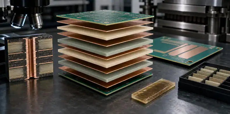
At incoming inspection, control material identifiers, lots, storage, copper type, core thickness, glass style, and resin content. Confirm that the returned stackup matches the constructions in the signal-integrity model.
During fabrication, the process plan should address lamination temperature history, pressure and vacuum records, resin flow, pressed thickness, registration, drill tool control, hole-wall preparation, desmear, plating, and copper treatment. The correct values come from supplier guidance and the fabricator’s qualified equipment—not from a general internet recipe.
Close the loop with evidence matched to the risks:
| Risk | Useful control | Verification evidence |
|---|---|---|
| Impedance or loss drift | Approved construction and copper profile | Coupons, TDR, and insertion-loss data where required |
| Hole-wall defects | Qualified drilling and desmear process | Microsections and acceptance criteria |
| Lamination variation | Recorded press cycle and material lots | Finished thickness, registration, and cure evidence |
| Thermal damage | Controlled moisture and assembly profile | Reflow simulation, microsections, or cycling plan |
| Unapproved substitution | Exact grade and change-notice rule | Certificate of conformance and traveler traceability |
For a complex build, QueenEMS’ multilayer PCB manufacturing requirements can help align the returned stackup, coupons, via plan, and inspection package.
When Should You Evaluate a Lower-Loss Material?
Evaluate a lower-loss material when the proposed IT-150DA construction fails the channel budget or lacks enough production margin—not merely because the interface name sounds fast. Data rate, modulation, rise time, Nyquist frequency, routing length, copper roughness, connectors, vias, and equalization all influence the outcome. The PCB material selector for Dk, Df, and Tg can organize candidates before construction-level data is requested.
Set a measurable trigger before comparing laminates. It might be a maximum modeled insertion loss at specified frequencies, a minimum eye margin, a compliance mask, or measured coupon performance. Then change one or more controllable contributors and rerun the same model.
A lower-Df material can be appropriate when dielectric loss is the limiting contributor. It may not fix a channel dominated by rough copper, long via stubs, connector discontinuities, poor reference transitions, or routing geometry. Likewise, moving to IT-968 because its roadmap number is lower does not remove the need for construction data and validation.
Also confirm that a lower-loss candidate is available in the required cores, prepregs, resin contents, copper types, region, and approved sites. An unbuildable stackup does not increase production margin.
The final selection should compare at least two buildable stackups under common solver assumptions and, for critical channels, a shared coupon or test plan. That creates evidence for the material decision without inventing a universal threshold such as “use IT-150DA up to 25G and upgrade above it.”
What Belongs in an IT-150DA PCB Material RFQ?
An IT-150DA RFQ should bind the material identity to the electrical model, board construction, assembly exposure, compliance needs, and approval process. “IT-150DA or equivalent” is too open unless the document also defines what equivalence means and who can authorize a change.
Include these inputs in the issue package:
- exact laminate/prepreg callouts and the governing ITEQ datasheet revision;
- finished thickness, layers, copper, minimum spacing, holes, and proposed stackup;
- core/prepreg codes, glass styles, resin content, and pressed thickness;
- impedance, interfaces, route lengths, loss targets, and solver assumptions;
- assembly profile, cycles, moisture handling, and rework expectation;
- IPC, UL, substance, customer, test, site, traceability, and change-control requirements.
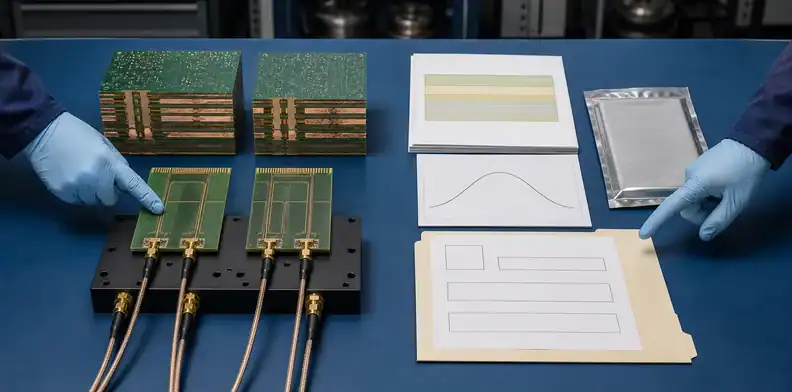
Ask each bidder to return a buildable stackup rather than merely accepting the drawing note. The response should distinguish supplier catalog typicals, fabricator design values, and finished-board acceptance limits. If an alternate is proposed, require matched evidence for the exact construction, a revised impedance and loss model, compliance documents, and written approval before use.
Engineering should approve performance and stackup, quality should approve evidence and change control, and purchasing should compare terms only after the technical proposals are comparable.
For a production quotation, send QueenEMS the fabrication files, controlled stackup, material revision, assembly profile, quantities, and substitution rule. The resulting quote should state the proposed construction and any open material-approval work so engineering and purchasing can make the same decision.
FAQ
Can I treat the 150 in IT-150DA as a 150°C Tg rating?
No. ITEQ’s current datasheet lists Tg at 180°C by DSC. Use IT-150DA as the grade identifier and keep the official property value and test method in the specification.
Does lead-free status prove every substance requirement?
No. Lead-free status answers one requirement only. Request a current grade-specific declaration whenever the project imposes another restricted-substance limit.
Can I use Dk 3.64 directly in my impedance solver?
No. The 3.64 value is typical at 10 GHz and 50% resin content under the stated IPC method. Use construction-specific design Dk from the laminate supplier and fabricator, including glass style, cured resin content, copper, and the solver’s method.
How do I know whether IT-150DA is enough for my data rate?
Model the actual channel and compare it with a defined loss or eye-margin limit. There is no authoritative universal data-rate cutoff because length, copper roughness, vias, connectors, geometry, and equalization can matter as much as the laminate Df.
Can a fabricator substitute FR408HR or I-Speed automatically?
No. Similar published properties or shared IPC slash sheets do not prove a drop-in substitution. Require a returned stackup, recalculated impedance and loss, thermal and compliance evidence, and written approval for the exact alternate construction.
Sources
- ITEQ IT-150DA official product page
- ITEQ IT-150DA official datasheet, W-CTE-1002-16B
- ITEQ official product map
- Isola FR408HR official datasheet
- Isola I-Speed official datasheet
Written by the QueenEMS Engineering Team
Upload your files today · Free DFM check before production · Ship worldwide
Get your PCB prototypes in as fast as 24 hours. We handle FR4, Rogers, and Flex up to 60 layers — free prototypes for 2–4 layer boards, no minimum order.
Just upload your Gerber + BOM — we source every part, assemble, and inspect (AOI + X‑Ray) so you don't have to chase suppliers. Boards ship in as fast as 24 hours.