
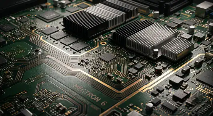
Megtron 6 vs Tachyon 100G is a channel-design decision, not a contest between two isolated Df numbers. Megtron 6 is Panasonic’s family of low-loss laminate and prepreg materials; Tachyon 100G is Isola’s separate laminate family. A useful comparison holds the stackup, copper, frequency and test method in view, then asks whether an alternative improves the finished-channel loss budget enough to justify qualification.
This article focuses on the cross-material decision and upgrade trigger. For a full explanation of Panasonic variants, properties and base qualification, see the separate Megtron 6 PCB material guide. A material data sheet is an input to the decision; it is not a substitute for a stackup model or a measured coupon.
What must stay comparable across the material quotes?
Panasonic lists R-5775 laminates and matching R-5670 prepregs in several variants. The Panasonic Megtron 6 family page distinguishes the low-Dk-glass N variant from standard-glass K and G variants. It also lists specialist constructions. A purchase order that says only “Megtron 6” leaves room for different glass, resin content, copper profile and core thickness to be quoted.
| Decision input | What to specify or request | Why it matters |
|---|---|---|
| Laminate and prepreg | Exact R-5775 and R-5670 suffixes, plus approved alternates | Variants are not interchangeable solely because they share a family name. |
| Core and prepreg build | Glass style, ply count, finished dielectric thickness and resin content | The effective dielectric behavior depends on construction. |
| Copper | Foil type/profile, starting and finished copper weight | Conductor roughness and geometry contribute to insertion loss. |
| Electrical evidence | Datasheet version and frequency, field-solver model, impedance and insertion-loss coupon plan | Single-frequency Dk or Df cannot establish the loss of a routed channel. |
For example, Panasonic’s published R-5775(N) data sheet reports typical Dk 3.34 and Df 0.0037 at 13 GHz for its stated sample and method. Its R-5775(K) data sheet reports typical Dk 3.62 and Df 0.0046 at 13 GHz under the stated method. These are material data-sheet values, not guaranteed finished-board or channel values. Do not compare a 1 GHz figure from one sheet with a 13 GHz figure from another as if they were measured on the same basis.
When should the qualified Megtron 6 stackup remain the baseline?
It is worth evaluating when a design needs lower dielectric loss than ordinary high-Tg FR-4 and the fabricator can supply a qualified Megtron 6 construction. Panasonic identifies networking, wireless, measuring instruments and other ICT equipment as applications. That does not mean every board in those systems uses the same Megtron 6 grade.
The practical question is whether the longest relevant channel meets its insertion-loss, impedance and manufacturing margins. Give the signal-integrity engineer the intended trace geometry, via transitions, connector model, copper profile and operating frequency. Ask the fabricator for a buildable stackup and coupon plan. If the simulated or measured channel meets the budget with appropriate margin, there is no engineering reason to upgrade solely because a newer material exists.
How should you compare Megtron 6 with Tachyon 100G or Megtron 8?
Compare equivalent constructions and the same measurement conditions. Isola’s Tachyon 100G product data contains Dk/Df values by construction and frequency. Panasonic publishes separate Megtron 6 variants and later Megtron families. A lower listed Df may improve dielectric-loss headroom, but the actual benefit also depends on copper, trace length, dielectric thickness, vias, fabrication process and test method.
| If the design team sees… | Next check |
|---|---|
| Megtron 6 channel passes with margin | Keep the qualified construction and verify supply, cost and process capability. |
| Loss margin is small or negative | Confirm model inputs and connector/via loss, then compare same-geometry coupons on candidate materials. |
| Higher-speed roadmap is planned | Set the future channel budget and test structures before preselecting a material family. |
| Second-source requirement | Qualify an alternate by stackup, impedance, insertion loss and reliability evidence, not by an “M-grade” label alone. |
A data rate such as 56G, 112G or 224G does not create a universal material pass/fail line. Channel reach, modulation, equalization, connectors and loss allocation all matter. If you need a direct material comparison, use the Tachyon 100G guide as background, then request comparable supplier data for the actual construction.
What should the PCB fabricator verify?
Before release, ask for the proposed layer stack, material suffix on every dielectric layer, core/prepreg availability, copper foil, finished thickness and impedance calculation. Define which nets or layers need loss control. Set the coupon geometry and reporting frequency alongside the acceptance rule. A measured coupon is useful only if it represents the production stackup and the agreed test method.

Also confirm drill, desmear, lamination and thermal-cycle qualification with the selected fabricator. Do not assume that a recipe proven for one Megtron 6 construction transfers unchanged to another material or a thicker board. When the design uses a hybrid stackup, identify which layers are Megtron 6 and which are other materials; review bond, thermal and registration constraints rather than treating the hybrid as a cost-only substitution.
Example: make the decision from a channel budget
Illustrative method, not a QueenEMS customer result: Suppose a board has a long channel close to its loss limit. The team first freezes connector and via models, then asks for two buildable stackups using the same trace geometry and copper profile. It simulates both, fabricates comparable coupons and measures insertion loss at the frequencies used in the channel budget. If Megtron 6 passes with margin, the team keeps the qualified material. If it does not, it evaluates the alternative’s measured improvement against procurement and manufacturing changes. Without those inputs, a claim such as “Megtron 6 fails beyond a certain number of inches” is not defensible.
Megtron 6 RFQ checklist
- Provide the exact laminate/prepreg suffixes or ask the fabricator to propose and disclose them.
- Attach stackup, finished board thickness, copper weights, foil requirements and controlled-impedance nets.
- State channel-loss targets, test frequencies, coupon design and acceptable reporting method.
- Identify high-speed layers, via transitions and any hybrid-material interfaces.
- Request material availability, approved alternates and the evidence required before substitution.
QueenEMS can review a proposed stackup and fabrication RFQ against these inputs. Send the layer drawing, channel-loss target and material constraints through the contact form; we can identify missing specification items before quoting. For the broader electrical-test workflow, see our controlled-impedance PCB guide.
Sources and limits
The material-family and typical electrical values above come from Panasonic’s linked product pages and data sheets; Tachyon information comes from Isola’s linked product page. Typical values are construction- and method-specific. The selection workflow is engineering analysis, not a claim of measured QueenEMS performance or a guaranteed material equivalence.
Upload your files today · Free DFM check before production · Ship worldwide
Get your PCB prototypes in as fast as 24 hours. We handle FR4, Rogers, and hybrid boards up to 40 layers in volume production, with advanced builds subject to engineering review — free prototypes for 2–4 layer FR-4 boards, no minimum order.
Just upload your Gerber + BOM — we source every part, assemble, and inspect (AOI + X‑Ray) so you don't have to chase suppliers. Boards ship in as fast as 24 hours.