
Many hardware engineers struggle with severe signal degradation and thermal limits when routing 224G PAM4 transceivers on AI server backplanes. Standard laminates simply cannot prevent data distortion at these extreme frequencies, forcing layout teams to constantly redesign their high-speed channels. The implementation of the M9 CCL specification solves this exact physics problem by pushing dissipation factors down to an absolute baseline.
Table of Contents
- What Is M9 CCL and Why Did NVIDIA Define a New Material Grade?
- How Does the M-Series CCL Grade System Work, from M4 to M10?
- What Electrical Properties Set This Grade Apart from M8 and M7?
- Why Does M9 CCL Require Q-Glass Instead of NE-Glass?
- What Role Do HVLP4 and HVLP5 Copper Foils Play in Its Performance?
- How Does This Next-Generation CCL Compare to M8 in Real Designs?
- Which Suppliers Actually Deliver M9 CCL at Production Volume?
- Where Does NVIDIA Use This Material Across Rubin and CPX?
- What Are the Fabrication Challenges of Building Ultra-Low-Loss Boards?
- How Will the Upcoming M10 Transition Reshape AI PCB Manufacturing?
What Is M9 CCL and Why Did NVIDIA Define a New Material Grade?
What exactly is this specification and why does the industry need it? NVIDIA defined M9 CCL as a strict internal performance standard for printed circuit boards targeting a dissipation factor (Df) of ≤ 0.0007 at 10 GHz. This classification dictates specific resin, glass, and copper pairings to guarantee signal integrity for high-bandwidth AI hardware.
Is This a Panasonic Part Number?
Many procurement teams mistakenly ask factories to buy this material from Panasonic. The truth is that Panasonic’s official product catalog currently caps out at Megtron 8, leaving this new tier to other specialized chemical vendors. Consider the reality:
- The M-series functions exactly like the AEC-Q100 industry standard.
- It operates as an OEM-driven specification across multiple suppliers.
- Current leading iterations come from Doosan, EMC, and Shengyi. Key Takeaway: Treating this specification as a set of physical requirements rather than a brand name helps your engineering team qualify the right suppliers without being locked into non-existent part numbers.
| Specification Type | Originator | Target Df | Manufacturer Scope |
|---|---|---|---|
| M8 Grade | Internal NVIDIA Spec | 0.0012 | Broad (Panasonic, EMC) |
| M9 Grade | Internal NVIDIA Spec | ≤ 0.0007 | Niche (Doosan, Shengyi) |
| Analysis: The specification shifts the industry focus from single-vendor reliance to a universal metric of extreme signal preservation. | |||
| Bottom line: This specification represents a highly controlled set of electrical demands across multiple laminate manufacturers, not a specific product line. |
How Does the M-Series CCL Grade System Work, from M4 to M10?
How does the industry categorize these varying levels of laminate performance? The system scales high-speed board performance by progressively lowering allowable Df thresholds, moving from M4’s 0.005 rating all the way to M10’s projected <0.0005 rating. You can evaluate your M9 CCL requirements by mapping them directly against your target data rates and channel lengths.
Mapping the Generations
Older architectures relied heavily on M4 and M6 materials for basic routing needs. Today, Panasonic’s Megtron 8 (R-5795) datasheet specifies a Df of 0.0012 at 10 GHz, completely dominating the current M8 tier for GB200 Bianca boards. Look at the evolution:
- M4 aligns with E-glass and RTF foils for mid-tier routers.
- M6 utilizes NE-glass and HVLP2 for 400G switches.
- M8 utilizes NER-glass and HVLP3+ for 1.6T environments. Key Takeaway: Understanding where your project falls on this scale prevents you from overpaying for unnecessary material specifications on slower digital boards.
Aligning with IPC Standards
While the M-grade naming convention remains a private specification, the underlying laminate properties align closely with standard industry metrics. The parameters map directly to IPC-4103 slash sheets, where /230 and /530 categories dictate progressively tighter Df limits. If you require high-layer-count PCB capability, these standards dictate the baseline testing methodologies your factory must execute. Key Takeaway: Referencing standard IPC slash sheets helps your QA department verify incoming material properties when direct OEM documentation remains classified.
| Laminate Tier | Representative Product | Glass Type | Copper Type |
|---|---|---|---|
| M6 | Megtron 6 / Tachyon | NE-Glass | HVLP2 |
| M8 | Megtron 8 / EM-892K2 | NER-Glass | HVLP3+ |
| M9 | DS-7409DYQ / M9Q | Q-Glass | HVLP4 |
| Analysis: Every sequential jump in this system forces a fundamental change in the physical components comprising the base laminate. | |||
| Bottom line: The grade system functions as a rigid roadmap for high-speed material properties, scaling precisely with the bandwidth demands of modern GPUs. |
What Electrical Properties Set This Grade Apart from M8 and M7?
What specific electrical values justify the massive cost of upgrading to this new standard? This grade separates itself by delivering an ultra-low dissipation factor of ≤0.0007 at 10 GHz, drastically cutting insertion loss per inch at extreme frequencies. Fabricators achieve these numbers by blending polyphenylene oxide (PPO) resins with customized hardeners rather than relying on legacy PTFE systems.
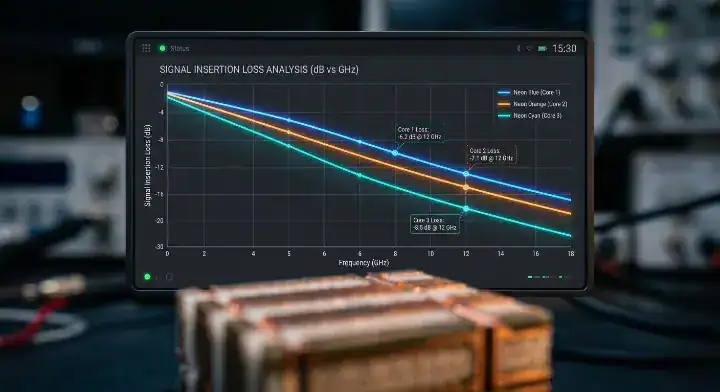
Comparing Insertion Loss
When operating backplanes at 56 GHz and beyond, physical trace attenuation completely dictates your component layout. Testing M8 at 28 GHz typically yields an insertion loss of roughly 0.50 dB/inch. Review the performance data:
- M8 at 28 GHz: ~0.50 dB/inch attenuation.
- M9 at 28 GHz: ~0.35 to 0.40 dB/inch attenuation.
- Delta: Up to 30% reduction in pure signal loss. Key Takeaway: This massive reduction in dB loss allows hardware layout teams to position transceivers further apart without introducing active retimers.
The PPO Resin Advantage
Maintaining FR-4-like processing compatibility remains vital for massive 78-layer boards. The PPO resin architecture provides the electrical performance of PTFE while surviving standard multi-press sequential lamination cycles. We detailed similar base chemistries in our previous coverage of Tachyon 100G, which also relies on thermoset properties rather than pure Teflon. Key Takeaway: Selecting PPO-based laminates keeps your fabrication costs grounded by utilizing standard pressing equipment instead of specialized RF microwave lines.
| Electrical Metric | M7 Grade | M8 Grade | New Spec |
|---|---|---|---|
| Df @ 10 GHz | 0.0016 | 0.0012 | ≤ 0.0007 |
| Dk @ 10 GHz | 3.3 | 3.1 | < 3.0 |
| Analysis: Pushing the dissipation factor below the 0.001 barrier acts as the primary catalyst for stable 224G communication. | |||
| Bottom line: The transition to this tier is purely driven by the absolute necessity to keep 28 GHz insertion loss below 0.40 dB/inch across long traces. |
Why Does M9 CCL Require Q-Glass Instead of NE-Glass?
Can fabricators reach these aggressive targets using standard low-loss glass weaves? Fabricators must use Q-glass because its intrinsic Df of 0.0005 is the only reinforcement capable of meeting the total laminate target of ≤0.0007. If you specify M9 CCL on your bill of materials, you are automatically mandating the use of this highly specialized quartz fiber.
Can You Still Use NE-Glass?
Many analysts and designers ask if they can simply use Megtron 8’s NE-glass structure to save money. Q-glass is a quartz-fiber reinforcement with an intrinsic dissipation factor of 0.0005, roughly half of NE-glass’s 0.001 baseline. Here is the physics limit:
- NE-glass starts at 0.001 Df before adding resin.
- The final pressed laminate will always exceed the glass baseline.
- NE-glass physically cannot achieve a sub-0.0007 result. Key Takeaway: You must completely abandon NE-glass structures if your layout demands the insertion loss profiles of the highest-tier AI servers.
The Supply Chain Reality
The shift to quartz-blended materials creates a massive bottleneck in raw supply and manufacturing budgets. Q-glass carries a massive premium, costing 1.7 to 2 times more than NE-glass and upwards of 15 times more than standard E-glass. Nittobo dominates this specific quartz supply chain, tightly controlling the global output available to laminate factories. Key Takeaway: Hardware managers must secure their Q-glass allocations months before attempting a pilot run of their new backplanes.
| Glass Type | Intrinsic Df | Relative Cost Multiplier | Usage Level |
|---|---|---|---|
| E-Glass | ~0.020 | 1x | Base FR-4 |
| NE-Glass | ~0.001 | 8x | M8 Grade |
| Q-Glass | ~0.0005 | 15x+ | M9 Grade |
| Analysis: The mandatory switch to quartz fiber fundamentally alters the cost structure of the raw bare board prior to assembly. | |||
| Bottom line: Achieving the ultimate low-loss specification is physically impossible without absorbing the extreme cost and allocation limits of Q-glass. |
What Role Do HVLP4 and HVLP5 Copper Foils Play in Its Performance?
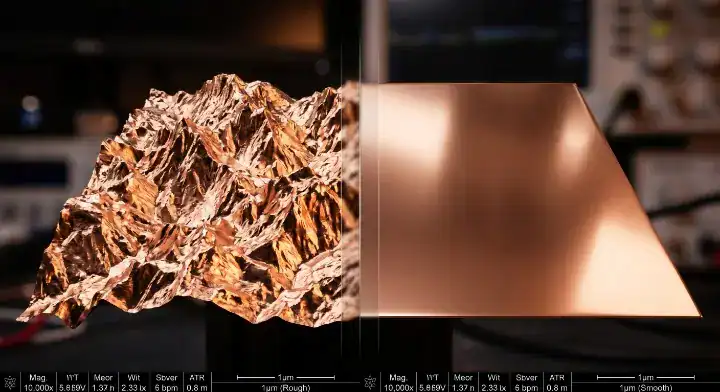
Why do factories obsess over microscopic copper roughness on these specific boards? These advanced foils mitigate the skin effect at extreme frequencies by strictly limiting surface roughness (Rz) to ≤ 1.0 µm or ≤ 0.6 µm. High-frequency digital signals travel entirely along the outer edge of the copper trace, making jagged foil profiles highly destructive to data integrity.
Mitigating the Skin Effect
Standard RTF copper creates microscopic “teeth” that force the 56 GHz signal to travel a physically longer, bouncing path along the trace boundary. Upgrading to HVLP4 completely flattens this interface, preventing phase shift and resistance spikes on differential pairs. If you plan to execute HDI PCB fabrication, perfectly flat copper also improves laser drilling precision for microvias. Here are the foil requirements:
- Standard RTF fails immediately past 10 GHz.
- HVLP3 supports M8 with a roughness near 1.5 µm.
- HVLP4/5 limits roughness under 1.0 µm for 224G links. Key Takeaway: Specifying the correct resin means nothing if you allow your fabricator to substitute a rougher copper foil during pressing.
Profiling Rz Values
The Rz value measures the peak-to-valley height of the treated copper nodule bonded to the dielectric. By dropping the Rz to ≤ 0.6 µm with HVLP5, fabricators virtually eliminate surface-scattering losses on the innermost stripline layers. This ultra-smooth profile requires highly specialized chemical adhesion promoters to prevent the layers from peeling apart during thermal stress. Key Takeaway: You must demand strict peel-strength testing on your coupons to verify that these ultra-smooth foils will survive assembly reflow.
| Copper Foil Type | Max Rz Value | Signal Behavior | Required Adhesion |
|---|---|---|---|
| HVLP3 | ≤ 1.5 µm | Moderate Skin Effect | Standard |
| HVLP4 | ≤ 1.0 µm | Low Skin Effect | High |
| HVLP5 | ≤ 0.6 µm | Near Zero Skin Effect | Specialized |
| Analysis: Eliminating copper roughness reclaims up to 15% of your total channel budget that would otherwise be lost to resistance. | |||
| Bottom line: Ultra-smooth HVLP4 and HVLP5 foils are absolutely mandatory components to extract the full electrical capability of the PPO resin. |
How Does This Next-Generation CCL Compare to M8 in Real Designs?
Can engineering teams survive using the older tier if they cannot secure the new material? While the new standard dominates 224G applications, M8 still functions flawlessly for 112G PAM4 channels shorter than 20 inches. Deciding whether to utilize M9 CCL depends entirely on the physical routing distance of your longest SerDes link.
A Hyperscale Case Study
A recent project we built for a hyperscale AI customer used M8-grade material for a 26-layer compute board with 112 Gbps PAM4 routed on six inner layers. The customer’s SI team originally specified the new standard, but material allocation was 12 weeks out and they needed the build in five. Our channel-loss simulation against the actual M8 stackup showed an insertion loss of 0.52 dB/inch at 28 GHz. Review the exact field numbers:
- M8 delivered 0.52 dB/inch actual loss.
- The 22-inch trace consumed 11.4 dB of the 14 dB budget.
- The system retained roughly 1.5 dB of safe margin. Key Takeaway: Simulating your exact trace lengths against actual factory stackups can prove that an M8 substitute meets your margin requirements safely.
Running the Channel Loss Math
The hyperscale customer kept the M8 build for first-article production and is now qualifying the higher-grade boards for mass volume. Upgrading the panels would have dropped the loss to roughly 0.36 dB/inch, freeing up 3 dB of massive margin for heavy connectors. Validating this math is why we conduct rigorous DFM reviews as part of our high-speed PCB manufacturing capability. Key Takeaway: If your longest high-speed trace sits under 20 inches, you can likely skip the allocation nightmare and launch prototypes on M8.
This is exactly why M8-grade material continues to anchor the entire current Blackwell platform. NVIDIA’s GB200 Bianca, GB300 UBB, and GB300 OAM boards all run on the same M8-grade allocation strategy described above. For the full layer-by-layer breakdown across each Blackwell board, see our complete Blackwell PCB material guide
| Board Spec | Trace Length | M8 dB Loss | Upgraded dB Loss |
|---|---|---|---|
| AI Compute | 12 inches | ~6.2 dB | ~4.3 dB |
| Midplane | 22 inches | ~11.4 dB | ~7.9 dB |
| Analysis: The performance gap mathematically widens as the physical trace length extends, making the upgrade mandatory for massive backplanes. | |||
| Bottom line: M8 remains a highly viable and practical substitute for 112G PAM4 designs provided your total channel length remains appropriately constrained. |
Which Suppliers Actually Deliver M9 CCL at Production Volume?
Can independent fabricators buy these specialized laminates from normal distribution channels? Doosan currently leads the global market with its DS-7409 M9Q series, while most other legacy manufacturers remain stuck in prototype testing. Hardware startups quickly discover that this tier of M9 CCL remains locked behind strict OEM allocation programs.
Can You Buy Prototype Sheets?
A major pain point for medium-sized fab shops and hardware founders is the absolute lack of open-market availability. You cannot simply walk in and purchase these laminates; they are currently restricted to specific NVIDIA, Google, and AWS qualification tracks. Here is the sourcing reality:
- You need an OEM introduction letter to secure sheets.
- You must place significant minimum volume orders.
- Lead times frequently stretch beyond three months. Key Takeaway: Build your initial proof-of-concept AI boards on readily available M8 variants, then qualify the extreme low-loss material during mass production readiness.
Tracking the Vendor Landscape
Doosan’s official CCL product portfolio publicly includes the DS-7409 family, with the DYQ/DCQ variants dominating the volume supply for this exact tier. Meanwhile, Shengyi is aggressively developing equivalents to capture the switch tray market, and EMC pushes its EM-896K3 to close the technical gap. The current environment heavily favors Korean suppliers tied into the massive HBM ecosystem. Key Takeaway: Tracking which laminate vendor holds the current volume lead helps your procurement team forecast realistic lead times for your hardware.
| Laminate Supplier | Product Line | Status in this Tier | OEM Priority |
|---|---|---|---|
| Doosan | DS-7409 M9Q | Volume Leader | High |
| Shengyi | S-Series Dev | Testing Phase | Medium |
| EMC | EM-896K3 | Development | Low |
| Analysis: The extreme difficulty of manufacturing Q-glass prepregs naturally creates a temporary monopoly for the few vendors who master the chemistry. | |||
| Bottom line: Doosan currently acts as the gatekeeper for volume production, and independent shops will struggle to source this material without hyperscaler backing. |
Where Does NVIDIA Use This Material Across Rubin and CPX?
Are hyperscalers applying this expensive laminate to every single circuit board in the rack? NVIDIA absolutely mandates this laminate for the massive 78-layer Rubin Ultra orthogonal backplane, but aggressively evaluates downgrades for peripheral interconnects to manage budgets. Strategic placement of M9 CCL prevents the total hardware bill of materials from exploding uncontrollably.
Did the Rubin Platform Downgrade?
The market reacted aggressively when 2026 reports suggested NVIDIA was pulling back from a full implementation across the Rubin server ecosystem. While the original 2025 roadmap called for full integration, reality forced severe compromises due to Q-glass shortages and low drilling yields. Consider the exact platform changes:
- Rubin Ultra backplanes remain fully committed.
- CPX boards reportedly downgraded to M8 equivalents.
- CX9 interconnects shifted down to M7 variants. Key Takeaway: Designing an AI rack requires a modular material strategy where only the most critical, longest interconnects receive the most expensive laminates.
Analyzing the M8.5 Transition
Industry sources reported by DigiTimes in January 2026 indicate that NVIDIA is evaluating an “M8.5-grade” intermediate specification to balance cost and performance. This transitional spec likely combines NER-glass with advanced HVLP4 foils to hit a ~0.0010 Df without the massive cost penalty of full quartz fiber. It proves that even the largest tech companies must negotiate with the laws of manufacturing economics. Key Takeaway: Preparing stackup designs that can rapidly switch between 8.5 and 9-class laminates protects your product launch from sudden supply chain shortages.
| Rubin Component | Original Spec | Updated 2026 Spec | Primary Reason |
|---|---|---|---|
| Ultra Backplane | Top Tier | Top Tier | Extreme trace length |
| CPX Board | Top Tier | M8 Grade | Cost / Yield balance |
| Midplane | Top Tier | M8.5 Eval | Q-Glass allocation |
| Analysis: The selective downgrading of secondary boards proves that extreme low-loss materials are reserved purely for the most critical signal bottlenecks. | |||
| Bottom line: The rollout is highly targeted by board function, abandoning the blanket-upgrade strategy in favor of precise, cost-effective engineering. |
What Are the Fabrication Challenges of Building Ultra-Low-Loss Boards?
Why do conventional PCB factories struggle to yield reliable boards with these specialized prepregs? Processing these laminates drastically cuts drill-bit lifespans by up to 70% and requires highly customized lamination profiles. The same quartz fibers that provide flawless signal integrity act like microscopic armor against standard mechanical cutting tools.
Why Do Drill Bits Fail Faster?
When we first ran a board approaching this grade with a quartz-blended glass system, our drill-bit consumption tripled compared to the equivalent NE-glass build. Quartz fiber is mechanically much harder—hitting roughly 7 on the Mohs hardness scale versus 6 for borosilicate glass. Our standard tungsten carbide drills completely wore out at roughly 800 hits instead of the usual 2,500 to 3,000 strikes. Here is the factory solution:
- We transitioned to expensive coated drill bits.
- We reduced mechanical drilling RPM by 30%.
- We implemented stricter hole-wall roughness inspections. Key Takeaway: You must verify that your chosen fabricator adjusts their drilling hit-counts and speeds, otherwise your internal via walls will fracture and fail.
Managing Lamination Pressures
Lamination presented the other major surprise, as Q-glass prepregs exhibit significantly lower resin flow at standard operational pressures. Trapped air pockets near the via barrels showed up heavily in cross-section inspection on the first batch. We solved this by adding a 5-minute vacuum hold at 80°C before ramping pressure, and by increasing the platen-to-platen pressure by 15%. Key Takeaway: Selecting a factory that actively recalibrates their thermal pressing cycles guarantees your multi-layer AI boards won’t delaminate under heavy thermal loads.
| Fabrication Step | Standard FR-4 | Quartz-Blended Spec | Impact |
|---|---|---|---|
| Drill Tool Life | 3,000 hits | < 800 hits | 2x Tooling Cost |
| Drilling RPM | Standard | Reduced 30% | Slower Throughput |
| Lamination | Standard Profile | +15% Pressure | Custom NRE Required |
| Analysis: Achieving high production yield on these boards relies entirely on slowing down the machines and constantly replacing the cutting mechanics. | |||
| Bottom line: The extreme physical hardness of quartz prepreg forces fabricators to reinvent their baseline drilling and pressing parameters to prevent catastrophic board failure. |
How Will the Upcoming M10 Transition Reshape AI PCB Manufacturing?
What happens when 224G speeds push current laminates past their absolute breaking point? The impending M10 transition will force dissipation factors below 0.0005, requiring factories to adopt upgraded quartz blends and HVLP5+ foils. As you evaluate your long-term M9 CCL usage, you must also prepare your supply chain for the next logical leap in materials physics.
Preparing for Sub-0.0005 Df
By early 2026, laminate vendors will push prototype test coupons attempting to break the <0.0005 Df barrier reliably at 10 GHz. This requires eliminating nearly all impurities in the PPO resin and weaving even finer quartz strands to guarantee total dielectric uniformity. Review the technical trajectory:
- M8 perfected NER-glass implementations.
- Current tiers validate early Q-glass volume.
- M10 will demand zero-profile copper and advanced quartz. Key Takeaway: Engineering teams must establish strong feedback loops with their fabricators today to secure early access to next-generation test coupons.
The Timeline for Feynman
Market roadmaps indicate that full volume production for this future tier aims for late 2027 to align perfectly with the NVIDIA Feynman platform. The lessons factories learn today regarding drill wear and thermal lamination will directly dictate their ability to yield these future boards. If a factory cannot reliably process today’s quartz specifications, they will completely fail to build the 2027 architectures. Key Takeaway: Auditing your fabricator’s current quartz-handling capabilities serves as the ultimate litmus test for their future relevance in the AI hardware sector.
| AI Platform | Target Year | Primary Laminate Spec | Network Speed |
|---|---|---|---|
| Blackwell | 2024 | M8 Grade | 112G PAM4 |
| Rubin | 2026 | New Grade / M8.5 | 224G PAM4 |
| Feynman | 2027+ | M10 Expected | 224G+ |
| Analysis: The aggressive cadence of GPU releases forces laminate chemistry to advance faster than conventional fabrication equipment can comfortably handle. | |||
| Bottom line: The next phase of PCB manufacturing will demand unprecedented cooperation between chemical vendors and bare-board fabricators to conquer the sub-0.0005 physics barrier. |
Conclusion
Navigating the extreme physics of 224G transceivers requires an absolute command over your stackup materials and factory capabilities. By understanding that this new specification relies on PPO resins, expensive Q-glass, and ultra-smooth copper, your engineering team can make accurate decisions regarding budget, availability, and signal margin. We bridge the gap between aggressive SI simulations and actual factory-floor yields, proving our high-layer-count PCB capability on every build. If your hardware roadmap demands ultra-low-loss performance without the allocation headaches, contact us today to review your layout. QueenEMS stands firm in delivering transparent, data-driven fabrication solutions that protect your signal integrity and your production timeline.
FAQ
Can I buy M9 CCL for a prototype build? Not from the open market. This specific grade is currently OEM-allocated to NVIDIA, Google, and AWS qualification programs. For prototype work targeting 112 Gbps PAM4 channels, build on M8-grade material (Megtron 8, EM-892K2, or equivalent), then qualify the higher tier in a later batch when volume justifies the allocation request.
What’s the real difference between M8 and M9 CCL in dB/inch? Roughly 30-40% lower insertion loss. M8-grade lands around 0.50-0.55 dB/inch at 28 GHz on stripline; the new specification lands around 0.35-0.40 dB/inch. Over 22 inches of trace, that is a 3 dB margin difference — highly significant if you are running 224G PAM4 or long backplane channels, but marginal if you are under 12 inches.
How do I know if my fab can actually build M9 CCL boards? Ask three concrete questions. One, do they hold Q-glass prepreg inventory or is it customer-supplied? Two, what is their drill-bit lifetime on Q-glass — anything under 600 hits per bit signals limited experience. Three, can they show coupon-level S-parameter data on M8 or higher builds. Vague answers on any of these mean the shop is not yet qualified.
Did NVIDIA really downgrade Rubin from M9 to M8? Partially, not fully. As of January 2026, market reports indicate CPX boards may downgrade to M8, CX9 interconnect to M7, and midplanes to M8. The Ultra orthogonal backplane remains locked to the highest tier. The manufacturer is also evaluating an 8.5-grade intermediate spec, making the full picture mixed by board rather than a blanket downgrade.
What’s the best alternative if my project can’t access M9 supply? M8-grade materials. Panasonic Megtron 8, EMC EM-892K2, Doosan DS-7409DJN+, and Shengyi S-series M8 products all offer Df around 0.0012-0.0015 at 10 GHz and are available without extreme OEM allocation. For channels under 20 inches at 112G PAM4, this tier typically delivers adequate margin.