
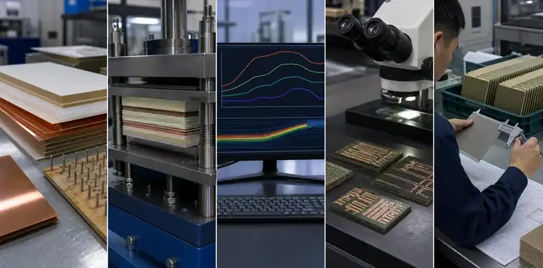
Quick Answer: BT substrate lamination bonds BT cores, prepregs, copper layers, and build-up structures under controlled heat, pressure, and cure conditions. The main engineering goal is to achieve the target thickness and registration while preventing voids, resin-flow defects, delamination, and warpage.
Key takeaways
- BT layup planning is about stack symmetry, resin flow, copper balance, core or coreless choice, and sequential build-up risk.
- Lamination settings are supplier-controlled, but buyers should specify thickness, material family, copper distribution, and warpage requirements.
- Coreless and thin BT builds can support low-height packages, yet they increase handling and flatness risk.
- A quote should ask for stack-up, material revision, lamination route, and inspection evidence instead of only a finished price.
Lamination is the part of BT fabrication where a drawing becomes a physical stack. It is also where many future problems start: bow, twist, voids, resin starvation, registration shift, and delamination. This article focuses only on BT lamination and layup. For the complete fabrication sequence, use the full BT manufacturing process. For the wider topic map, the BT PCB guide connects this point to specifications, applications, sourcing, and quote preparation.
| Layup factor | What it affects | Buyer check |
|---|---|---|
| Copper balance | Bow and twist | Dense areas marked for review |
| Prepreg choice | Thickness and resin flow | Material family named in quote |
| Sequential build-up | Registration and cost | Need justified by routing |
| Lamination risk | Visible symptom | Useful evidence |
|---|---|---|
| Resin starvation | Local weakness | Cross-section or stack review |
| Trapped voids | Reflow reliability concern | Inspection plan |
| Residual stress | Warpage after profile | Flatness measurement |
Table of Contents
- How BT substrate lamination works
- What goes into BT layup planning?
- Lamination temperature and cure profile
- Choosing prepreg and resin content
- Why symmetric stackups matter for warpage
- Coreless and sequential lamination
- What to send for a BT lamination review
- How to compare BT layup proposals
- How to freeze the accepted lamination stack
How BT substrate lamination works
A BT substrate is laminated by stacking BT cores, prepregs, copper foils, and build-up layers in a defined order, then bonding them under heat and pressure. The supplier controls thermal ramp, pressure, vacuum or press condition, dwell, and cool-down profile so resin flows and cures without voids or excessive residual stress. Decision signal: The buyer owns the stack requirement; the fabricator owns the lamination recipe that can meet it.
What goes into BT layup planning?
BT layup planning includes layer order, copper balance, prepreg choice, resin flow, core thickness, build-up dielectric, via positions, and dense copper locations. A thin substrate with heavy copper on one side and sparse copper on the other is likely to move during cure and reflow. For thickness planning, see BT thickness and layer count. Layup rule: A BT stack should be evaluated as a mechanical system, not only as a list of copper layers.
Lamination temperature and cure profile
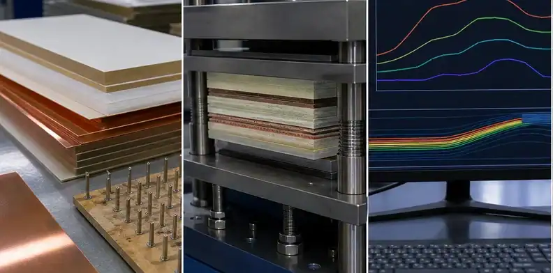
Lamination temperature and cure profile depend on the BT material system and supplier process. Buyers should avoid copying a generic temperature into a drawing because the correct profile belongs to the material supplier and fabricator. Ask whether the quoted material has a defined cure profile, controlled pressure, and inspection for voids or delamination. Cure rule: Do not put a guessed BT lamination temperature into the RFQ; request the supplier’s validated process boundary instead.
Choosing prepreg and resin content
Prepreg choice affects resin flow, dielectric spacing, thickness, copper fill, and dimensional behavior. MGC’s BT lineup includes laminate and prepreg families for IC plastic packages, with thin prepreg options in low-CTE material lines. The buyer should state finished dielectric thickness, impedance or RF needs, CTE target, and coreless expectation. Material check: Prepreg is not a commodity spacer in BT; it is a process and flatness control element.

Why symmetric stackups matter for warpage
Symmetric stackups matter because each layer expands, shrinks, and stores stress during lamination and reflow. A balanced stack reduces bending between copper, resin, glass, die attach, and later assembly materials. The dedicated controlling BT warpage article covers the wider flatness problem. Warpage signal: If copper and dielectric are not balanced on paper, do not expect lamination alone to rescue flatness.
Coreless and sequential lamination
Coreless BT construction is used when the package needs very low height or special routing density. Removing the core can help thickness, but it reduces stiffness and increases handling sensitivity. Sequential lamination appears when the design builds additional layers in stages, often to support microvias and fine pitch. QueenEMS’ HDI lamination capabilities and sequential lamination cost pages explain adjacent trade-offs. Build rule: Coreless and sequential BT should be treated as engineering choices, not default upgrades.
What to send for a BT lamination review
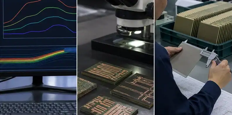
Send the stack-up, copper distribution, finished thickness, material target, via plan, warpage limit, controlled impedance or RF constraints, panel size, and assembly reflow condition. If the substrate carries a die or package, include die size, attach method, mold or lid information, and coplanarity requirement. Keep the layup decision attached to the released stack so resin flow, copper balance, via structure, and flatness evidence stay in one controlled package.
Extra buyer notes for lamination defects
Lamination defects are often invisible until a later step exposes them. Small voids can become reliability concerns after reflow, poor resin flow can create local thickness changes, and residual stress can appear as warpage only after singulation. A buyer should not assume that a clean-looking panel proves the layup is stable.
Dense copper areas deserve a separate review. Power islands, shields, ground pours, and local copper thieving can change resin flow and stress. A supplier may suggest copper balancing, but the design owner must check whether the change affects RF behavior, sensor performance, impedance, or customer-approved geometry. In package substrates, even nonfunctional copper can have electrical side effects.
The stack-up should show which layers are cores, which are prepregs, and which are build-up layers. Without that distinction, two suppliers may quote different lamination routes under the same layer count. One quote may be cheaper because it assumes a simpler press cycle, while another may be more realistic for the microvia and thickness target.
For repeat orders, lock the material revision and lamination assumption. A small change in prepreg type or resin flow can alter thickness and flatness. The supplier may consider the change equivalent from a purchasing view, but the assembly owner may see a different coplanarity result.
Void prevention should be discussed when the design includes dense copper, blind vias, or tight dielectric spacing. Voids may not be obvious on the surface, but they can become weak points during thermal cycling or reflow. Ask the supplier what inspection evidence is reasonable for the risk level instead of assuming a standard visual check is enough.
Registration drift is another lamination outcome. Cores, prepregs, and copper layers move during heat and pressure, and the final shift can affect via capture or bond-pad alignment. The buyer should mark critical registration features so the supplier knows which tolerances are functional and which are ordinary fabrication dimensions.
Sequential lamination changes both cost and risk because each press cycle adds another opportunity for movement. If the supplier proposes an extra sequential step to solve routing, ask whether a different fanout, layer count, or microvia structure would be more stable. The cheapest stack is not always the lowest-risk stack after assembly.
Coreless layup should include a handling plan. A very thin carrier may need temporary support through build-up, finish, profiling, and shipping. If the supplier cannot explain how the substrate is handled without deformation, the buyer should treat the coreless option as incomplete.
For package programs, the lamination review should happen before final artwork release. Once tooling and first articles are made, changing dielectric thickness or copper balance can affect electrical performance, mechanical height, and qualification evidence. Early review saves more time than late repair.
Lamination review questions that actually change the quote
The first question is whether the stack is balanced enough to press and assemble. A supplier can often fabricate an asymmetric stack, but the buyer needs to know whether it creates warpage, registration, or yield risk. Ask the supplier to mark the worst copper imbalance rather than giving a general statement about stack symmetry.
The second question is whether the dielectric spacing is controlled by available prepreg or by a special construction. If the design requires an unusual dielectric thickness, the supplier may need a different prepreg combination or an extra lamination step. That changes both lead time and repeatability.
The third question is whether the via structure forces sequential lamination. Some designs can be routed with one lamination cycle and laser vias. Others need staged build-up. Sequential lamination may be technically correct, but the buyer should understand the cost, schedule, and registration consequences before approving the stack.
The fourth question is how the supplier prevents voids around dense copper. Resin has to flow into spaces and around copper features during pressing. If copper density changes abruptly, resin behavior becomes less predictable. The supplier may suggest copper balancing, adjusted prepreg, or modified panel layout to improve flow.
The fifth question is what evidence will prove lamination quality. Depending on risk, evidence may include cross-section, thickness measurement, visual inspection, warpage data, or a first-article stack report. The buyer should avoid requesting every possible report by default, but a high-risk package should not ship with only a generic certificate.
Layup examples that change engineering approval
A balanced four-layer BT carrier may be straightforward if copper density is similar above and below the centerline. The supplier still needs material and thickness control, but the warpage risk is easier to manage. This kind of stack can often move through quotation with a normal DFM review.
A thin sensor carrier with copper concentrated on one face is different. The substrate may bow after lamination or reflow, even when the electrical pattern is correct. Engineering should review whether copper balancing or a thicker construction is possible before approving the quote.
A coreless package carrier changes the handling question. The design may meet the height target, but the supplier must support it through build, finish, profile, packing, and assembly. If the supplier cannot describe that path, the quote should stay in engineering review.
A sequential build-up stack should be justified by routing need. Extra lamination cycles can solve microvia escape, but they add registration, cost, and lead-time risk. The buyer should ask whether a different fanout or layer plan could avoid a process step.
For every case, the release note should identify the accepted stack and the reason it was accepted. That keeps repeat lots from drifting when a different buyer, engineer, or supplier contact handles the next order.
What a good layup response looks like
A good layup response does not need to reveal the press recipe. It should state whether the stack is balanced, whether the material set is standard, whether sequential lamination is required, and whether the supplier sees a warpage or void concern. That gives the buyer enough information to approve the route or ask for a design change.
For a thin package substrate, ask the supplier to identify the most sensitive layer pair. The answer might point to a dense copper layer, a thin dielectric, a via transition, or an asymmetric area near the die. That specific risk is more useful than a generic statement that lamination will be controlled.
The buyer should also ask whether repeat lots require the same panel size or array plan. Changing panelization can change stress, registration, and handling. If the first lot proves the process, the repeat order should preserve the assumptions that made it stable.
Finally, keep lamination evidence proportional. A simple build may need only stack confirmation and outgoing inspection. A high-density package carrier may need cross-section, thickness data, and warpage measurement. The goal is useful proof, not paperwork for its own sake.
A final layup check is moisture handling before pressing. Thin BT materials and prepregs should be stored and staged under supplier-controlled conditions. If a material waits too long before lamination or absorbs moisture, voids, flow behavior, and final flatness can change. The buyer does not need to police the factory floor, but the supplier should be able to describe normal material control when the package is sensitive.
Ask whether any customer-controlled dimensions depend directly on lamination. Finished thickness, dielectric spacing, and via registration may all be affected by press behavior. If those dimensions are critical, they should be measured and reported rather than assumed from nominal stack-up.
For early prototypes, it can be useful to request the supplier’s preferred stack adjustment before locking the drawing. A small change in dielectric thickness, copper balance, or layer order may improve lamination yield without changing the product function. Once the pilot lot starts, those changes become harder because electrical and mechanical evidence may already be tied to the first stack.
How to compare BT layup proposals
Compare layup proposals by stack balance, prepreg availability, sequential lamination need, and inspection evidence. A slightly thicker or more balanced stack can be the better production choice when flatness matters.
How to freeze the accepted lamination stack
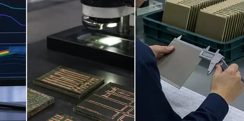
Freeze the accepted layup by recording the stack revision, material family, thickness range, copper balance, and any supplier-approved adjustment. That record keeps a repeat order from drifting into a different prepreg, copper distribution, or flatness assumption after the first pilot build is accepted.
For a layup review, send the proposed BT stack, copper distribution, prepreg or core preference, via plan, thickness limit, and flatness requirement through QueenEMS contact. QueenEMS can judge whether BT layup build support is ready for quotation or needs a stack balance adjustment first.
FAQ
How is BT laminated?
BT is laminated by pressing cores, prepregs, copper, and build-up layers under controlled heat, pressure, and cure conditions.
Why is symmetric layup important?
Symmetry reduces residual stress and warpage, especially in thin BT substrates that must stay flat during reflow.
What is coreless BT layup?
Coreless BT removes the stabilizing core to reduce thickness, but it increases handling and flatness risk.
Should buyers specify the cure temperature?
Usually no. Buyers should state performance and evidence requirements; the supplier should use a validated material-specific cure profile.
Sources
- Mitsubishi Gas Chemical, Low-CTE BT resin laminate lineup
- Global Electronics Association, IPC-6921 organic IC substrate standard
Written by the QueenEMS Engineering Team
Upload your files today · Free DFM check before production · Ship worldwide
Get your PCB prototypes in as fast as 24 hours. We handle FR4, Rogers, and Flex up to 60 layers — free prototypes for 2–4 layer boards, no minimum order.
Just upload your Gerber + BOM — we source every part, assemble, and inspect (AOI + X‑Ray) so you don't have to chase suppliers. Boards ship in as fast as 24 hours.