

Medical device PCB fabrication costs more than a commercial board for two reasons: the board itself is often built to a stricter class with more testing, and the device maker’s quality system requires documentation, traceability and change control from the supplier. The cost that can safely come out is in the design and the specification, not in the controls: fewer layers and lamination cycles, standard materials and finishes, tolerances only where they matter, efficient panels, and a test and document scope that matches the device’s risk. Settle those before the first quote, because once a board is validated, every later change has to go through the device’s change control.
| Cost driver | Where to save | Where not to |
|---|---|---|
| Layer count and lamination cycles | Remove layers the routing does not need | Planes that hold impedance or isolation |
| Performance class | Class 3 only where the risk file needs it | Class 3 required by the device design |
| Materials | Standard high-Tg FR-4 where it is enough | Materials validated in the design |
| Tolerances | Standard values except on critical features | Impedance, fit and isolation features |
| HDI features | Through-holes where routing allows | Microvias the BGA escape needs |
| Testing and documents | Scope matched to device risk | Records your QMS requires |
Which Rules Apply to Medical PCBs?
Three layers of requirements meet at the bare board, and only one of them is written for the board itself:
- Device safety standards such as IEC 60601-1 set basic safety and essential performance for medical electrical equipment (IEC 60601-1). They apply to the finished device, and drive board features like creepage, insulation and materials, but they do not certify a PCB factory.
- Quality system rules govern how the device maker controls suppliers. ISO 13485 is the international standard, and in the United States the FDA’s Quality Management System Regulation in 21 CFR Part 820 now incorporates ISO 13485 by reference (FDA on the QMSR).
- Board standards: IPC-6012 sets performance requirements for rigid boards. Its medical addendum (IPC-6012EM for the E revision) applies only when the purchase documents name it (IPC-6012F contents, clause 1.3.1.3).
“Medical” does not automatically mean IPC Class 3. A patient monitor’s display board and an implant have very different risk, and the class should come from the device’s risk analysis.

What Drives Medical PCB Cost?
The same things as any board, plus the cost of evidence. The construction items are layer count, number of lamination cycles, material, board size and panel use, smallest features, via types, finish and quantity. On top of those come Class 3 inspection, more electrical and microsection testing, first-article reports, lot traceability and the supplier’s time on change notifications.
For implantable and very small devices, the medical addendum adds categories of miniaturization. IPC’s announcement of IPC-6012EM described coverage from ordinary diagnostic boards to very small, high-density boards that may be implanted, including a level for line widths and spaces under 60 µm and via structures under 100 µm (IPC on IPC-6012EM, 2020). Most medical boards are nowhere near that level and should not pay for it.
When Can Layer Count Be Reduced?
When the routing and electrical design still work with fewer layers, which is worth checking before the first build. Each pair of layers adds material, and each extra lamination cycle in an HDI build adds process steps and yield risk. Look for signal layers carrying only a few nets, planes that could be shared, and microvias that through-holes could replace if parts were moved.
Do not remove planes that set impedance, return paths or isolation barriers, and do not compress spacing on isolated circuits to save a layer: those are the features a device safety review will look at. After validation, a layer change is a design change that needs re-verification, so it rarely pays off later.
Which Tolerances and Features Should Be Relaxed First?
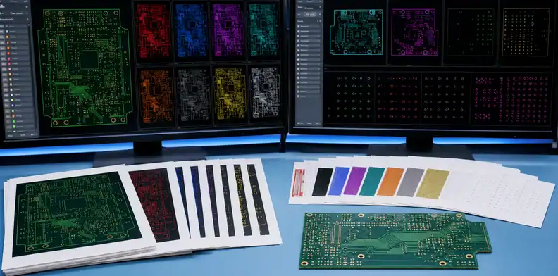
The ones that do not affect function. Tight tolerances on board outline, hole positions, solder mask and legend often come from a template rather than the design. Keep tight tolerances on controlled impedance, connector fit, press-fit holes and isolation spacing; return everything else to the fabricator’s standard values. Our guide to which PCB tolerances are worth paying for covers the common ones.
Via structures are the next lever. Microvias, via-in-pad and stacked vias are justified under fine-pitch BGAs, but each adds process steps; if a part can move or a larger-pitch package is available, a through-hole design costs less. Our DFM guide covers the layout checks that keep a board in the standard process window.
Do Medical Boards Need Special Materials?
Usually not. Most medical electronics run on standard high-Tg FR-4, the same family as industrial products. As an example of what such a laminate offers, Isola lists FR406 with a Tg of 170 °C, a Td of 300 °C and Z-axis expansion of 60 ppm/°C below Tg, in cores from 2 to 125 mil and copper from ½ to 2 oz (Isola FR406). Specialty laminates, flex and polyimide make sense when the device needs them, for example for wearables or high-frequency imaging, not by default.
What matters for a medical program is that the material stays the same. Name the laminate on the drawing and require notification before any substitution; a change made for availability can trigger re-verification.
Which Tests and Documents Should Be Quoted?
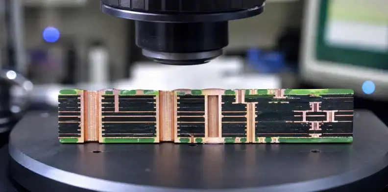
The ones your quality system and risk file actually require, agreed before the quote so they are priced in. Typical items:
| Item | When it is needed |
|---|---|
| 100% electrical test | Almost always |
| Certificate of conformance | Every lot |
| Microsection report | Class 3, HDI, or as the risk file requires |
| Impedance test report | Controlled-impedance designs |
| First-article inspection report | New part number or revision |
| Material and finish certificates | When the QMS requires material traceability |
| Lot traceability and date codes | Usually, for device history records |
| Change notification | Always for validated designs |

Asking for everything on every board raises cost without reducing risk. Which boards need the Class 3 package is covered in our Class 2 versus Class 3 article.
How Can Panelization Reduce Cost?
By fitting more boards on each production panel. Board price depends heavily on how many pieces fit on the fabricator’s working panel, so a small change in outline or an agreed panel array can lower unit cost without touching the design. Ask the fabricator for its panel utilization on your outline and whether rotating or nesting the board helps. For assembly panels, agree the array, rails and fiducials with the assembler so the fabricator’s panel and the assembly panel work together.
How Can We Help?
QueenEMS works under an ISO 9001:2015 quality system and builds to Class 2 or Class 3 of IPC-6012, with impedance control to ±5% and layer counts from 1 to 40. Send the drawing with the class, the test and document list your QMS requires, and the quantities by stage; we will point out features that move the board out of the standard process window, and the bare-board price is ready within 2 hours. Reference lead times for prototype and production builds are on our home page and confirmed in each quote.
Conclusion
| Goal | Action |
|---|---|
| Lower unit cost | Fewer layers and lamination cycles, standard material, better panel use |
| Avoid paying for unneeded rigor | Class and tests from the risk file, not by default |
| Keep validation intact | Lock material, stackup and supplier; require change notification |
| Price accurately | Agree tests and documents before quoting |
Make cost decisions in design and specification, before validation fixes them in place. Contact us with the Gerber files, drawing with class, test and document requirements, and the quantity plan.
FAQ
What is PCB fabrication? Making the bare circuit board: laminating, drilling, plating, imaging and finishing the copper layers, before any components are assembled.
Does a medical PCB have to be IPC Class 3? No. The class should come from the device’s risk analysis; many medical boards are Class 2.
Does the PCB supplier need ISO 13485? Not always. Your QMS decides which suppliers need it, based on what the part does in the device.
How much does a medical PCB cost? It depends on layers, size, features, class and quantity; ask for quotes on the same drawing, tests and documents.
Can I change a medical PCB supplier after validation? Yes, but it is a controlled change that usually needs verification of boards from the new source.
Upload your files today · Free DFM check before production · Ship worldwide
Get your PCB prototypes in as fast as 24 hours. We handle FR4, Rogers, and hybrid boards up to 40 layers in volume production, with advanced builds subject to engineering review — free prototypes for 2–4 layer FR-4 boards, no minimum order.
Just upload your Gerber + BOM — we source every part, assemble, and inspect (AOI + X‑Ray) so you don't have to chase suppliers. Boards ship in as fast as 24 hours.