
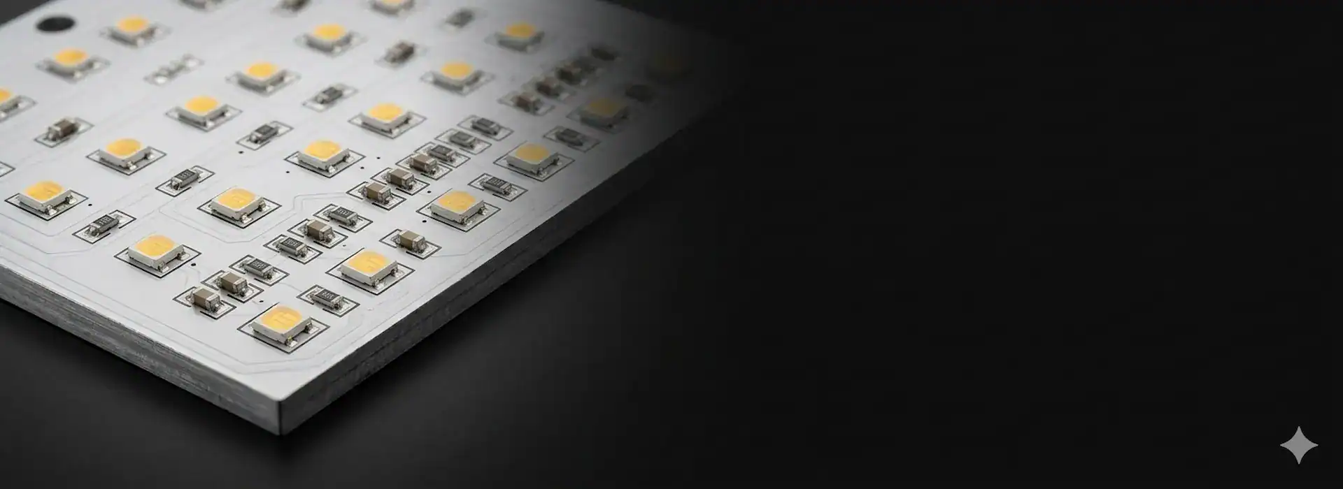
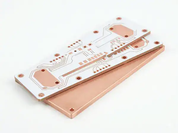
Professional Metal Core PCB Manufacturer & Assembly Factory
Direct factory supply. 100+ imported production machines. We engineer high-performance Metal Clad PCB solutions that eliminate thermal failure — so your power designs survive where standard FR4 cannot. Accurate quotes within 2 hours.
Get an Instant Quote
Sourcing Metal Based PCB? Avoid These 3 Costly Pitfalls
Cheap metal core boards fail silently — until your LEDs dim, your power modules overheat, or your production line grinds to a halt. Here's what experienced buyers watch for.
Fake Dielectric Layers
Some suppliers label their boards with premium thermal conductivity ratings while substituting low-cost insulation materials. The result: your critical power components overheat within months, causing field failures that destroy customer trust and trigger costly recalls.
Hidden Delivery Delays
Trading companies accept your order, then scramble to find a real factory behind the scenes. Without direct production control, your delivery timeline slips by weeks — putting your entire product launch and retail commitments at serious risk.
CTE Mismatch Cracking
When the thermal expansion coefficient of the metal base doesn't match the dielectric and copper layers, solder pads crack and delaminate under thermal cycling. Your boards pass initial QC but fail catastrophically in the field during temperature swings.
Don't gamble with your thermal management design. Work with a factory that engineers every layer.
Talk to Our Metal Core PCB EngineersFull-Lifecycle Metal Core PCB Fabrication Services
From single-piece rapid prototyping to 10,000+ volume production runs — with seamless PCBA assembly integration — we cover every stage of your metal substrate project.
Rapid Prototyping
Upload your Gerber files and receive functional Metal Core PCB prototypes in as few as 5 working days. Our dedicated quick-turn line uses in-stock aluminum and copper base materials, so you validate thermal performance before committing to volume — cutting weeks off your development cycle.
Volume Production
Scale seamlessly from prototype to mass production on the same calibrated production lines. Our 100+ imported machines maintain identical process parameters whether you order 50 or 50,000 panels — delivering batch-to-batch consistency that your quality team can rely on.
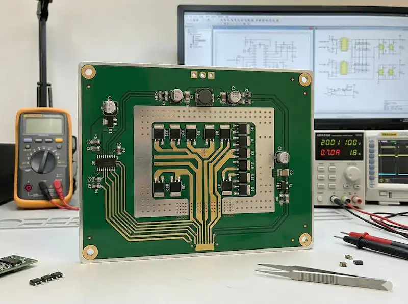
Turnkey PCBA Assembly
Eliminate multi-vendor coordination headaches. We combine our metal core board fabrication with in-house SMT and through-hole assembly, complete with thermal paste application and LED sorting. One purchase order, one factory, one accountable partner from bare board to tested assembly.
Ready to streamline your metal core PCB supply chain from prototype to production?
Request a Service ConsultationUnderstanding Insulated Metal Substrate (IMS) PCB
Standard FR4 boards trap heat. A Metal Core PCB replaces the fiberglass base with a thermally conductive metal — typically aluminum or copper — creating a direct heat dissipation path from your components to the heatsink.
Copper Foil Circuit Layer
The top copper layer carries your circuit traces and component pads. Thicker copper options (up to 6 oz) handle high-current paths in power supply and motor driver applications without excessive trace width.
Thermally Conductive Dielectric Layer
This is the critical performance layer. A high-quality dielectric (1.0–8.0 W/m·K) provides electrical insulation while conducting heat away from components at up to 20× the rate of standard FR4 prepreg.
Metal Base Layer (Aluminum / Copper)
The structural metal core acts as a built-in heatsink. Aluminum (150 W/m·K) suits most LED and power applications, while copper base (385 W/m·K) delivers extreme thermal performance for automotive-grade and high-power industrial modules.
Need help selecting the right metal base and dielectric for your thermal design?
Consult Our Thermal EngineersHigh-Performance Aluminum PCB Board & Copper Core Solutions
Every metal core PCB category is engineered to solve a specific thermal challenge. Choose the substrate that matches your power density, routing complexity, and operating environment.
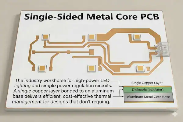
Single-Sided Metal Core PCB
The industry workhorse for high-power LED lighting and simple power regulation circuits. A single copper layer bonded to an aluminum base delivers efficient, cost-effective thermal management for designs that don't require complex multi-layer routing.
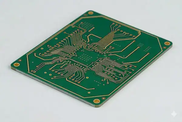
2-Layer Metal Core PCB
When your power circuit demands more routing real estate than a single side allows, our double-sided metal core boards provide two copper layers with plated through-holes — giving you the design freedom to route complex power control networks while maintaining superior heat extraction.
Copper Base PCB
For extreme thermal environments where aluminum simply can't keep up, copper base PCBs provide 2.5× the thermal conductivity. Designed for automotive-grade power modules, EV charging stations, and high-brightness laser diode applications that demand zero thermal compromise.
Not sure which metal substrate is right for your power design? Our engineers will recommend the optimal solution.
Upload Gerber for Free ReviewMetal Core PCB Design for Manufacturability Guide & Capabilities
Our engineering team reviews every design file against these production parameters before quoting. Matching your design to our proven capability window ensures first-pass success and eliminates costly re-spins.
| Parameter | Capability Range |
|---|---|
| Thermal Conductivity | 1.0 W/m·K – 8.0 W/m·K |
| Base Metal Options | Aluminum 5052 / 6061, C1100 Copper |
| Base Material Thickness | 0.4 mm – 3.0 mm |
| Copper Thickness | 1 oz – 6 oz (35 μm – 210 μm) |
| Board Layers | 1L / 2L / Multi-layer Hybrid |
| Min. Trace Width / Spacing | 100 / 100 μm (4 / 4 mil) |
| Min. Drill Size | 0.3 mm (12 mil) |
| Dielectric Breakdown Voltage | ≥ 3.0 kV (Hi-Pot tested) |
| Surface Finish | HASL, OSP, ENIG, Immersion Silver |
| Solder Mask Color | White, Black, Green, Blue, Red |
| Max. Panel Size | 500 × 600 mm |
Engineer's DFM Tips
Designing your first metal core PCB? Follow these guidelines to maximize yield and minimize your unit cost:
- Avoid drill holes smaller than 0.5 mm on single-sided aluminum boards — smaller vias risk cracking the dielectric during thermal cycling.
- Keep copper-to-edge clearance ≥ 0.5 mm to prevent short circuits between traces and the exposed metal base after routing.
- For thermal conductivity above 3.0 W/m·K, specify dielectric thickness ≤ 75 μm to maximize heat transfer efficiency.
- Use white solder mask for LED applications — it delivers 85%+ reflectivity, boosting your luminaire's optical efficiency at zero extra cost.
Submit your design files and our engineers will verify DFM compliance within 2 hours — free of charge.
Upload Gerber for Free DFM CheckWhere Are Our Metal Backed PCBs Used?
From stadium spotlights to electric vehicle charging stations, our metal core boards perform in the most thermally demanding environments across the globe.
Metal Core PCB for LED
High-power stage lighting, automotive headlights, and commercial luminaires generate intense heat that degrades LED chips. Our aluminum PCB boards extract this heat through the metal base directly to the heatsink, extending LED lifespan by up to 50,000 hours and maintaining consistent color temperature across the entire fixture.
Power Supply & Converters
Switching regulators and power converters concentrate heat in compact footprints. Our metal core substrates spread this thermal load evenly across the base layer, preventing hot spots that cause capacitor degradation and MOSFET derating — keeping your power supply running at full rated output without forced-air cooling.
Automotive & EV Applications
Motor controllers, IGBT driver boards, and EV charging station power modules operate under extreme thermal and vibration stress. Our copper base PCBs withstand continuous 150°C operating temperatures and pass automotive-grade thermal shock testing (-40°C to +150°C, 1000 cycles), ensuring zero solder joint failures over the vehicle's lifetime.
Tell us about your thermal challenge — we'll recommend the optimal metal core solution for your application.
Describe Your Project RequirementsWhy Pragmatic Buyers Choose QueenEMS as Their Metal Core PCB Supplier
We don't just manufacture boards — we engineer thermal solutions. Every advantage below translates directly into faster timelines, lower risk, and predictable costs for your project.
2-Hour Technical Quotation
Our in-house engineering team reviews your Gerber files, stack-up requirements, and thermal targets — then delivers a detailed technical quote within 2 business hours. You receive material recommendations, impedance feasibility notes, and realistic production timelines, not a generic price sheet. This means you can lock in budgets and finalize vendor decisions the same day.
Engineering-Driven Support
Your inquiry is handled by engineers who understand thermal conductivity, CTE matching, and dielectric breakdown testing — not order-takers. Our sales and engineering teams work as one unit, proactively flagging DFM issues, recommending optimal dielectric thickness, and suggesting cost-saving panelization layouts before your board enters production.
Zero-Gap Process Consistency
Whether you order 5 prototype panels or 10,000 production panels, every board runs through the same calibrated equipment with identical process parameters. Our dielectric bonding pressure, curing temperature, and V-cut depth remain locked at the same settings — so your volume order performs exactly like your approved prototype, with zero surprises at incoming inspection.
Experience the difference of working directly with a factory that leads with engineering, not sales talk.
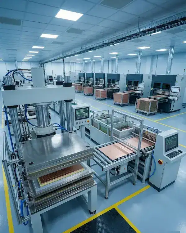
Get Your 2-Hour Technical QuoteInside Our Verified Metal Core PCB Facility in China
QueenEMS is a direct PCB manufacturer — not a trading company, not a broker. Our factory in Shenzhen runs dedicated aluminum and copper base production lines, separated from standard FR4 operations. This dedicated infrastructure means your metal core boards receive optimized lamination pressure, curing profiles, and routing parameters from day one.
100+
Imported Machines
20+
Years Experience
2 Hrs
Fast Quotation
50+
Countries Served
100% Inspection. Zero Compromise on Quality.
Metal core PCBs carry high-power loads in mission-critical applications. A single defective board can cause cascading thermal failures. Our multi-stage inspection protocol catches every issue before your boards leave our facility.
AOI Optical Inspection
Our automated optical inspection systems scan every panel at micron-level resolution, catching trace defects, solder mask misalignment, and copper surface contamination that manual inspection would miss. This ensures every circuit path on your metal core board is electrically reliable before it reaches the next production stage.
Hi-Pot Breakdown Test
Every metal core PCB undergoes high-voltage dielectric breakdown testing (Hi-Pot) at voltages exceeding 3.0 kV. This rigorous test verifies the insulation integrity between your copper circuit layer and the metal base, guaranteeing zero leakage current under the most demanding power operating conditions your end product will face.
100% E-Test & X-Ray
Flying probe testing verifies open/short on every net across your board. For multi-layer hybrid metal core designs, our internal X-Ray system inspects via fill quality and internal layer registration. Combined, these tests ensure your boards achieve a 100% electrical pass rate, preventing any defective units from entering your assembly line.
Request sample inspection reports and material certificates of analysis to verify our quality commitment firsthand.
Request Sample QC ReportsSecure Packaging Engineered for Heavy Metal Core Boards
Metal core PCBs are significantly heavier than standard FR4 boards. Without proper packaging, they arrive with scratched surfaces, bent edges, and cracked dielectric layers. Our packaging protocol is built specifically for metal substrates.
Vacuum-Sealed Moisture Barrier
Each panel stack is sealed in aluminum moisture barrier bags with desiccant packs and humidity indicator cards. This prevents oxidation on the metal base surface and dielectric moisture absorption during ocean freight — ensuring your boards arrive solder-ready without any pre-bake requirement.
Anti-Static Protection Layer
For PCBA shipments with mounted components, we wrap assemblies in ESD-shielding bags rated to MIL-PRF-81705. Combined with conductive foam inserts between boards, this dual-layer protection eliminates electrostatic discharge risks that could damage sensitive MOSFETs and LED drivers during handling and transit.
Reinforced Export Cartons
Metal core boards are 2–3× heavier than standard PCBs. We use multi-wall corrugated cartons with custom-cut PE foam dividers that cradle every panel individually. Corner protectors and compression-tested stacking ensure zero edge damage — even after 30+ days of ocean container transit across rough seas.
Every shipment arrives in perfect condition — guaranteed. Ask about our packaging specifications.
Learn About Our Shipping StandardsFast & Trackable Global Shipping
From quote to delivery, every milestone has a clear timeline. We partner with DHL, FedEx, UPS, and dedicated sea freight lines to keep your metal core PCB supply chain predictable and on schedule.
Technical Quotation
Submit your Gerber files and receive a detailed engineering quote with material and thermal recommendations — fast enough to finalize your vendor decision the same day.
Quick-Turn Prototyping
Validate your thermal design with functional prototypes using in-stock aluminum and copper base materials — without waiting for special material orders.
Mass Production
Full-volume production with Hi-Pot tested panels, comprehensive quality reports, and batch traceability — ready for your assembly line on schedule.
Global Express Delivery
Door-to-door tracked shipping via DHL, FedEx, or UPS. We also support DDP terms for hassle-free customs clearance in the EU, US, and major markets worldwide.
Need expedited delivery for an urgent production deadline?
Request Rush ProcessingCertified Reliability & Trusted by Market Leaders
Our quality system meets the world's most demanding industrial standards. Hear directly from procurement managers and engineers who have shipped production orders with us.
"QueenEMS solved our aluminum PCB delamination issue that two previous suppliers couldn't fix. Their dielectric testing and Hi-Pot reports gave our quality team full confidence. The 2-hour quotation response is a genuine competitive advantage — it saved us weeks of back-and-forth during our LED driver redesign."
David M.
Procurement Manager, Germany
"We switched to QueenEMS for our copper base IGBT driver boards after our previous supplier shipped boards with inconsistent thermal conductivity between batches. QueenEMS provides full material COAs and the prototype-to-production consistency has been flawless across three production runs."
Sarah L.
Hardware Engineer, United States
Join the engineers and procurement managers who source with confidence.
Become Our Next Success StoryFrequently Asked Questions about Metal Core PCBs
Quick technical answers for engineers and procurement professionals evaluating metal substrate solutions.
What is the difference between FR4 and Aluminum PCB Board?
Can you manufacture 2-layer metal core PCB with blind vias?
What files do I need to provide to get an accurate quote?
What thermal conductivity do I need for high-power LED applications?
What is your Minimum Order Quantity (MOQ)?
Do you provide DFM review for metal core PCB designs?
How do you ensure the dielectric layer quality is genuine?
How does the dielectric layer of an IMS PCB balance high thermal conductivity with electrical insulation?
What DFM considerations are critical for 2-layer Metal Core PCBs to avoid delamination?
How does QueenEMS verify the long-term reliability of Metal Clad PCBs for automotive or aerospace applications?
Can you handle urgent NPI (New Product Introduction) for complex Metal Based PCB designs?
Why should we choose Aluminum PCB over standard FR4 with heavy copper for LED projects?
How do you stabilize lead times for specialized materials like Copper Base or high-thermal substrates?
How can QueenEMS help reduce Time-to-Market for EV and power conversion products?
What ROI can we expect by upgrading to high-conductivity IMS PCB solutions?
Have a specific technical question about your metal core PCB design?
Ask Our Engineering TeamStop Waiting. Get Your Metal Core PCB Quote in 2 Hours.
Upload your design files and our engineers will perform a free DFM check, recommend the optimal dielectric and base metal, and deliver a detailed technical quote — all within 2 business hours.
Email Us
[email protected]
Response within 2 hours
Call / WhatsApp
+86-0755-363091328
Mon – Sat, 9AM–6PM CST
Visit Our Factory
1-4/F Property Office Building,
ZhengFeng North Road,
Shenzhen, China 518103
Head Office
1/27, Soi Border 5, Bang Bon Tai,
Bang Bon, Bangkok 10150, Thailand