
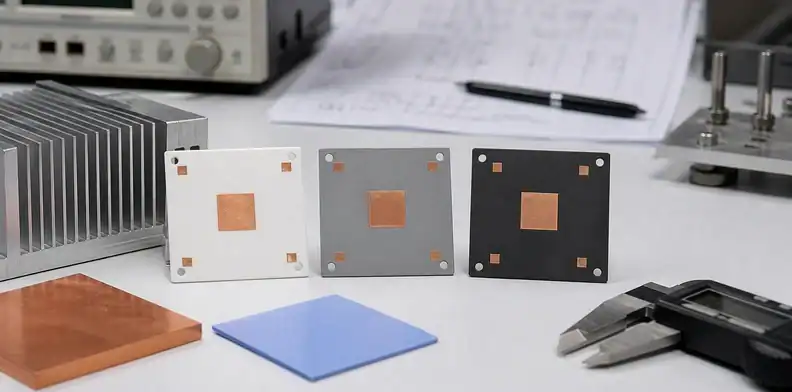
Quick Answer: Ceramic PCB thermal conductivity varies by grade and temperature. Rogers curamik examples at 20°C are 24 W/(m·K) for alumina, 170 for AlN, and 90 or 110 for Si3N4. Compare these named products in the table below, then use thickness and heat-flow area to calculate the ceramic layer’s resistance. Device temperature also depends on attachment, heat spreading and cooling.
- W/mK numbers compare ceramic materials; they do not directly predict junction temperature by themselves.
- Alumina, AlN, and Si3N4 answer different buying questions: cost, heat spreading, and reliability stress.
- A useful RFQ links thermal conductivity to substrate thickness, copper, finish, heat sink, and assembly evidence.
Thermal conductivity is one of the first numbers buyers ask for when comparing ceramic PCB materials. It is also one of the easiest numbers to misuse. A supplier may advertise an AlN value, another may quote alumina, and a third may mention Si3N4 for power modules. The buyer then tries to convert those numbers into a board decision without enough context.
Compare conductivity only after identifying the material and its measurement temperature. Then examine how ceramic thickness, heat-flow area, metallization and interfaces turn that property into an assembly temperature. A worked layer calculation makes the limits of a catalogue comparison visible.
Table of Contents
- What does ceramic PCB thermal conductivity actually measure?
- What are typical AlN, alumina, and Si3N4 numbers?
- Why does higher W/mK not always mean lower device temperature?
- When is alumina enough despite lower conductivity?
- When does AlN justify its cost?
- Where does Si3N4 fit if thermal conductivity is not highest?
- What should the RFQ say about thermal data?
- How should overseas buyers verify supplier claims?
What does ceramic PCB thermal conductivity actually measure?
Ceramic PCB thermal conductivity measures how readily the ceramic material conducts heat through its body under a defined test condition. It is usually expressed in W/mK, but the published value belongs to a material grade or substrate family, not automatically to a finished assembled product.
That distinction matters because a ceramic assembly includes more than its ceramic layer. The construction may contain metallization, surface finish, solder or die attach, a thermal interface and a heat sink. Identify which layers lie along the actual heat path and where heat can spread or take parallel routes. A high-conductivity ceramic can still leave excessive thermal resistance at the attachment or cooler interface.
The buyer should also check direction. Many simple comparisons assume heat flows through the ceramic thickness into a heat sink. Some layouts need lateral spreading before the heat reaches a mounting point. Copper pattern, backside metal, copper thickness, and device placement can change that path.
For sourcing, the useful question is not “what is the highest number?” It is “which material and construction keep the device temperature within the approved margin under the real assembly condition?”
What are typical AlN, alumina, and Si3N4 numbers?
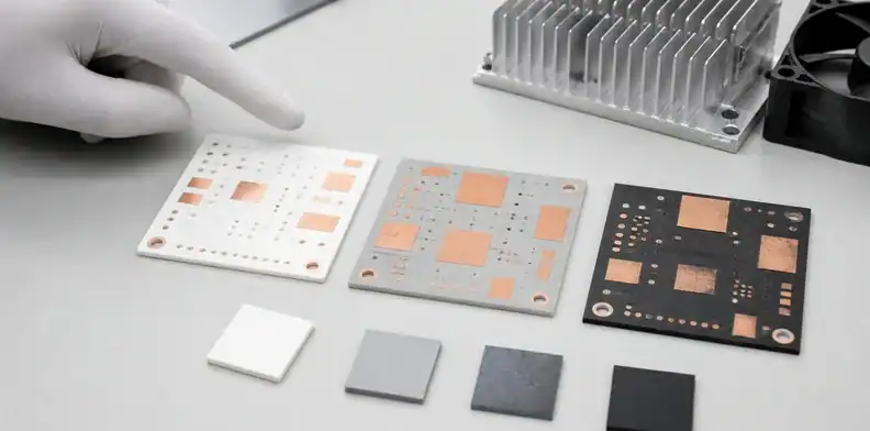
Typical ceramic PCB material comparisons place alumina in the cost-effective lower thermal-conductivity range, AlN in a much higher thermal-conductivity range, and Si3N4 in a reliability-focused range where strength and thermal cycling behavior are often central. Exact numbers vary by manufacturer, purity, grade, test method, and processing route.
The Ceramic PCB Guide places these conductivity values beside process and application limits, which prevents a datasheet number from being treated as the whole thermal decision.
The following examples come from the Rogers curamik product data sheet, ©2026. All listed conductivity values are at 20°C and identify a supplier product family. They provide a traceable comparison; they are not QueenEMS measurements or acceptance limits for an unnamed ceramic.
| Named product | Ceramic | Conductivity at 20°C |
|---|---|---|
| curamik Power | Alumina | 24 W/m·K |
| curamik Power Plus | Zirconia-toughened alumina, HPS | 26 W/m·K |
| curamik Performance | Silicon nitride | 90 W/m·K |
| curamik Performance Plus | Silicon nitride HiCon | 110 W/m·K |
| curamik Thermal | Aluminum nitride | 170 W/m·K |
Request the offered grade and its current property sheet when a value controls the design. A different supplier can use different grades, and operating-temperature conductivity may differ from these room-temperature entries. Keep typical material data separate from a lot-specific guarantee.
| Material family | How buyers usually read it | Practical sourcing meaning |
|---|---|---|
| Alumina | Lower thermal conductivity, mature supply | Good when heat density and cost target allow margin |
| AlN | Much higher thermal conductivity | Good when compact heat spreading is the bottleneck |
| Si3N4 | Reliability and strength are often the reason | Good when thermal cycling or ceramic fracture risk matters |
Kyocera and other ceramic manufacturers publish material-property tables for fine ceramics, but those tables should be read as material data. The final board result depends on substrate thickness, metallization, copper, finish, mounting, and assembly.
Why does higher W/mK not always mean lower device temperature?
Higher W/mK does not always produce a lower device temperature because the ceramic is only one thermal resistance in the path. A poor solder joint, thick dielectric path, weak heat-sink contact, small copper area, voided attach layer, or high interface resistance can erase much of the expected benefit.
Check thickness and area with a transparent layer model
For steady one-dimensional heat flow through a uniform layer, R = t/(kA). Use metres for thickness t, square metres for area A and W/m·K for conductivity k. The result is K/W. The model assumes ideal contact, constant properties and uniform heat flow; it excludes lateral spreading and the rest of the assembly.
As an illustration, use the 170 W/m·K AlN value above and an assumed 10 mm × 10 mm heat-flow area. A 0.63 mm layer gives 0.00063/(170 × 0.0001) = 0.0371 K/W. Reducing the assumed thickness to 0.32 mm gives 0.0188 K/W. Keeping 0.63 mm thickness but halving the area gives 0.0741 K/W. The alternative dimensions are calculation inputs, not a claim that all such constructions are available or suitable.
Those calculations can resolve a misleading quotation comparison. Imagine two AlN offers that list the same conductivity but differ in finished thickness. Recalculate only the ceramic term using the same heat-flow area before attributing the difference to a better material. If the package footprint is small, using the entire board outline as A would hide the spreading problem and make both offers look unrealistically favorable.
For the preferred construction, compare the predicted temperature with a representative populated sample using the documented heat-source and cooler conditions. If the measured device temperature remains much higher than expected, first reconcile the model boundary: attachment thickness, contact resistance and lateral spreading were excluded from the slab calculation. Inspect or characterize those contributions before demanding a still higher conductivity grade. A thinner ceramic may reduce its own resistance while changing insulation and mechanical requirements, so those checks remain part of approval. The lesson from the layer model is how to isolate a proposal’s contribution, not that halving ceramic thickness will halve the assembly temperature rise.
This is why a ceramic PCB RFQ should describe the whole heat path. Add the device package, power or loss estimate, mounting method, heat sink, thermal interface material, copper thickness, surface finish, ceramic thickness, assembly process, and whether any thermal test or inspection evidence is required.
The device owner should also define the acceptance metric. Is the target LED junction temperature, power device case temperature, module base temperature, enclosure temperature, or heat-sink rise? Each one places the measurement point in a different location.
When is alumina enough despite lower conductivity?
Alumina is adequate when a representative thermal model or measurement meets the temperature target and the selected construction also meets electrical, mechanical and cycling requirements. Available area and cooling can make its lower conductivity acceptable. A broad application label such as sensor or LED does not establish that margin.
For many LED, sensor, heater, isolation, and lower-power electronics projects, alumina may give enough margin. The buyer should confirm that with a thermal estimate or prototype test rather than assuming AlN is required. A premature upgrade can raise cost, extend sourcing time, and narrow supplier options.
Alumina is also useful during early prototypes. If the design is still proving component placement, enclosure contact, or assembly flow, a controlled alumina sample may reveal whether the thermal path is actually a problem. If it fails the target, the buyer can move to AlN with a clearer reason.
The RFQ should still name the alumina grade or class when available, thickness, copper route, finish, outline tolerance, flatness expectation, and assembly exposure. A low-cost alumina quote that hides those details is not comparable to a controlled AlN quote.
For high-power LED context, use the QueenEMS article on ceramic PCB for high-power LED and UV-C. The thermal number becomes useful only after the LED package and heat sink are known.
When does AlN justify its cost?
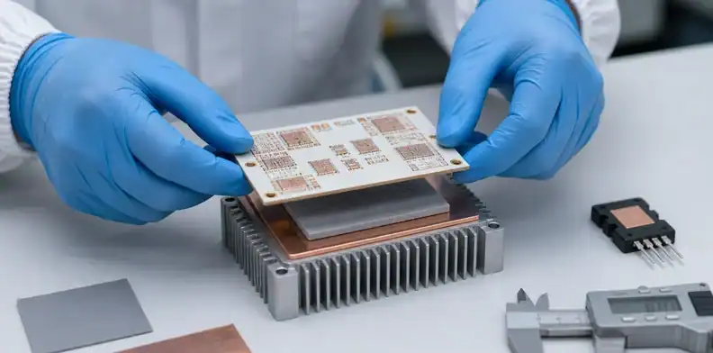
AlN justifies its cost when heat density, package size, device temperature, or cooling structure makes thermal conductivity the limiting constraint. It is most useful when the product cannot simply use more board area, lower current, a larger heat sink, or a looser lifetime target.
Common triggers include compact high-power LED modules, laser diode submounts, power electronics control islands, RF power modules, high-temperature sensors, and dense assemblies where local hot spots dominate the design. At equal thickness and heat-flow area, a higher-conductivity AlN grade reduces the ceramic layer’s thermal resistance relative to alumina. It does not physically shorten the heat path or remove the other interfaces.
The buyer should not approve AlN just because it sounds premium. Ask which AlN grade is being quoted, what thermal class the supplier claims, which copper or metallization route is used, and whether the surface finish and flatness support the intended assembly.
Kyocera’s AlN material pages position aluminum nitride as a high thermal-conductivity ceramic used for heat-dissipation applications. That is a material-level reason to shortlist AlN, but the buyer still needs board-level evidence.
Where does Si3N4 fit if thermal conductivity is not highest?
Si3N4 fits when reliability stress, ceramic strength, and thermal cycling risk matter more than chasing the highest W/mK number. In power electronics, silicon nitride is often discussed for AMB substrates because it can offer strong mechanical behavior under demanding cycling conditions.
That makes Si3N4 a different kind of answer. It may not win a simple thermal-conductivity table against AlN, but it may become attractive when the ceramic must survive copper stress, baseplate attachment, power cycling, or a customer qualification program. For some high-reliability power modules, the failure mode is not only heat flow; it is mechanical fatigue and cracking risk.
Buyers should connect the material to the failure mode. If the problem is only steady-state temperature, AlN may be the stronger comparison. If the problem is thermal cycling, copper bond stress, or ceramic fracture risk, Si3N4 AMB may deserve review.
Use the QueenEMS article on power-module substrate selection for the application-level module decision. This article only explains why W/mK is not the whole story.
What should the RFQ say about thermal data?
Use the following fields to request comparable thermal options. Keep the material property, finished geometry and assembly conditions in separate entries so a supplier can identify exactly which assumption changes between alternatives.
Avoid vague wording such as “best thermal conductivity ceramic PCB.” A better note says: “Please quote alumina and AlN options for this drawing. State ceramic grade, nominal thermal conductivity basis, ceramic thickness, copper route, surface finish, flatness, and any assembly or heat-sink assumption that affects thermal performance.”
If the project is production-bound, include change-control language. A supplier should not substitute ceramic grade, thickness, copper process, finish, or thermal interface assumption without engineering approval. Those changes can alter the thermal path even when the Gerber file is unchanged.
| RFQ field | Why it matters |
|---|---|
| Material grade | Prevents generic alumina or AlN claims |
| Ceramic thickness | Changes thermal resistance and mechanical behavior |
| Copper route | Controls spreading, adhesion, feature size, and cost |
| Surface finish | Affects soldering, attach, and storage |
| Heat-sink interface | Defines the real path out of the device |
| Evidence request | Converts a number into a supplier commitment |
The QueenEMS ceramic manufacturing overview explains the available construction categories. For a thermal comparison, narrow the enquiry to a named grade, its conductivity at the relevant temperature, and the finished dimensions. A generic material description leaves too much uncertainty in the calculated layer resistance.
How should overseas buyers verify supplier claims?
A material certificate and an assembled thermal test answer different questions. Before accepting a supplier’s thermal claim, identify whether it concerns the ceramic grade, the finished substrate or the populated module.
Assign responsibility for soldering or die attach, heat-sink mounting and thermal testing. A bare-substrate supplier may cover none of these operations; a PCB/PCBA partner may coordinate assembly without owning module qualification. Request results from the operation that controls the relevant interface, and keep the tested assembly revision with its temperature measurements.
FAQ
What is a good thermal conductivity for ceramic PCB?
A useful value identifies the grade and temperature. For example, Rogers curamik data at 20°C lists alumina at 24 W/m·K and AlN at 170 W/m·K, with Si3N4 products at 90 and 110 W/m·K. Those product examples do not determine a board temperature; thickness, heat spreading and interfaces still need evaluation.
Is AlN always better than alumina?
No. AlN has much higher thermal conductivity, but alumina can be better when the design has enough thermal margin and cost or availability matters. Compare the complete heat path, not only the material table.
Does ceramic PCB thermal conductivity predict junction temperature?
Not by itself. Junction temperature also depends on power loss, copper spreading, ceramic thickness, attach layer, thermal interface material, heat sink, airflow, and measurement point.
Why use Si3N4 if AlN has higher thermal conductivity?
Si3N4 may be reviewed when mechanical strength, thermal cycling, and ceramic fracture risk are central. It is often a reliability decision rather than a simple W/mK upgrade.
Send QueenEMS a ceramic thermal review package
Use QueenEMS’s quotation form to submit the device losses, layout, ceramic and copper dimensions, cooler interface, temperature target and proposed assembly. Request a named material grade and conductivity basis for each alternative, with any unknown thermal boundary stated explicitly. That makes the returned quotes usable in the same thermal comparison.
Sources
- Kyocera, Aluminum Nitride material properties
- Rogers Corporation, curamik ceramic substrates
Written by the QueenEMS Engineering Team
Upload your files today · Free DFM check before production · Ship worldwide
Get your PCB prototypes in as fast as 24 hours. We handle FR4, Rogers, and Flex up to 60 layers — free prototypes for 2–4 layer boards, no minimum order.
Just upload your Gerber + BOM — we source every part, assemble, and inspect (AOI + X‑Ray) so you don't have to chase suppliers. Boards ship in as fast as 24 hours.