
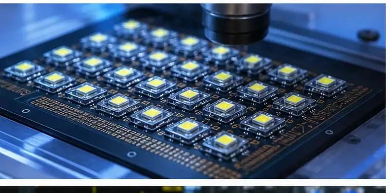
Quick Answer: BT PCB can fit LED and Mini-LED chip-package carriers, especially where compact routing, cost, and package processing matter. It is not the right primary thermal substrate for high-power LED heat removal; ceramic materials such as alumina or AlN usually win when thermal conductivity is the main problem.
Key takeaways
- BT belongs mainly in LED chip packaging and Mini-LED carrier contexts, not high-power heat-spreading boards.
- Thermal conductivity separates BT from ceramic: BT is organic and low-k thermally, while AlN is far higher.
- Mini-LED designs may use BT for dense chip carriers but still use metal or ceramic routes for heat-heavy backlights.
- The buyer should define whether the project is a package-density problem or a heat-removal problem.
LED buyers often ask about BT after seeing it in chip packaging, mobile modules, memory, or RF package substrates. The risk is using the word LED too broadly. A tiny LED chip carrier and a high-power lighting board do not need the same substrate. QueenEMS’ BT versus ceramic thermal trade-offs page covers the broad material comparison. This article narrows the question to LED and Mini-LED applications. For the wider topic map, the BT PCB guide connects this point to specifications, applications, sourcing, and quote preparation.
Table of Contents
- Is BT PCB used for LED applications?
- Where BT fits in LED chip packaging
- BT versus ceramic for LED heat
- Is BT suitable for Mini-LED?
- When high-power LED needs ceramic instead
- How cost compares for LED substrates
- What this means for your LED project
Is BT PCB used for LED applications?
BT PCB is used in some LED-related packaging, but it should not be treated as a universal LED thermal substrate.
The distinction is package carrier versus heat sink. BT can support compact chip-level routing and package processing. High-power LED boards usually need a stronger thermal route than organic BT can provide.
| LED project type | BT fit | Better alternate when heat dominates |
|---|---|---|
| LED chip carrier | Often possible when density and package process matter | Ceramic only if heat path requires it |
| Mini-LED package substrate | Possible for dense small-pitch carriers | Metal-core or ceramic for heat-heavy backlight structures |
| High-power LED module | Usually weak as the main thermal path | Alumina, AlN, DBC, or metal-base choices |
| Cost-sensitive display package | May be useful at package level | Review heat budget before choosing organic substrate |
Define the object being quoted: LED chip package, Mini-LED carrier, display module board, or high-power lighting substrate. That single description changes the material path.
This article does not cover LED driver circuit layout. It only decides whether BT is a sensible substrate family.
Buyer call: Use BT for LED package density; use ceramic or metal-base routes for serious heat removal.
Where BT fits in LED chip packaging
BT fits best where the LED problem is packaging density, electrical routing, and cost-sensitive carrier construction.
In chip-package use, the substrate may need fine features, low warpage, and semiconductor-package compatibility. BT’s role is to carry the chip and interconnects, not to act like an AlN heat spreader.
A buyer should send chip size, pitch, pad layout, optical package constraints, surface finish, and heat path notes. Without the heat path, the supplier cannot tell whether BT is the right carrier or only a cheaper but risky idea.
The word LED alone is too broad for material selection. The package architecture must be named.
Evidence rule: Select BT only when the LED substrate’s first job is package interconnect control.
BT versus ceramic for LED heat
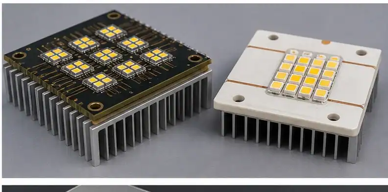
Ceramic wins when LED heat removal is the dominant design problem.
BT is an organic substrate with much lower thermal conductivity than ceramic. AlN ceramic can be around two orders of magnitude higher in thermal conductivity than organic BT, making it a better route for high-power thermal spreading.
If junction temperature, heat flux, or lumen maintenance controls the design, review ceramic LED substrate cost and the ceramic PCB for LED hub before approving BT.
BT can still appear in the package around the LED, but that is not the same as making it the main thermal board.
Engineering gate: When heat is the limiting metric, compare ceramic and metal-core designs before quoting BT.
Is BT suitable for Mini-LED?
Mini-LED can use BT in dense package-carrier roles, but the backlight or display system may still need another thermal solution.
Mini-LED raises density, routing, and package alignment demands. BT may support small carriers or chip-package substrates where electrical density and manufacturing cost matter. Larger backlight panels can have a separate heat-spreading challenge.
Separate the Mini-LED carrier from the thermal chassis. The RFQ should state whether QueenEMS is reviewing chip carrier, module board, or full backlight thermal structure.
Do not let the success of BT in one Mini-LED package imply it fits every Mini-LED board in the product.
Quote signal: Use BT in Mini-LED only where package density, not bulk heat flow, is the primary driver.
When high-power LED needs ceramic instead
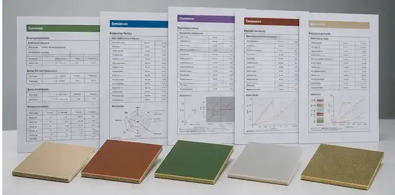
High-power LED usually points away from BT when the substrate must conduct heat directly from the LED.
High brightness, UV-C, dense power packages, and small thermal pads can overwhelm BT’s organic heat path. Ceramic or DBC/metal options may add cost, but they solve a different physical problem.
Ask for junction-temperature target, power per emitter, thermal interface, copper area, and expected heat-sink connection. Those data decide whether BT should stay in the package only or leave the design entirely.
A lower material price does not compensate for thermal failure or accelerated lumen degradation.
Release check: Reject BT as the main high-power LED thermal substrate when the heat budget cannot close.
How cost compares for LED substrates
BT can be cheaper than ceramic in package-style LED carriers, but cost must be tied to thermal risk.
A BT option may reduce material and process cost for compact chip carriers. Ceramic raises the bill but can prevent thermal redesign, qualification delay, or field reliability problems in high-power use.
The cost comparison should show two cases: package-density BT and heat-led ceramic. QueenEMS can quote both routes only after the heat path and package role are clear.
For wider thermal-cost comparison, use QueenEMS’ BT versus ceramic thermal trade-offs page.
Document rule: Compare LED substrate cost only after classifying the job as package carrier or heat spreader.
What this means for your LED project
The right LED substrate starts with the dominant constraint: routing density, package assembly, thermal conductivity, or module cost.
BT belongs in the conversation when the project resembles a semiconductor package. Ceramic belongs in the conversation when power density and thermal path control dominate.
Provide power per LED, package form, substrate size, copper or metallization requirement, heat-sink path, and quantity. That set allows an honest BT versus ceramic recommendation.
This avoids the common mistake of asking suppliers whether they can make LED BT without telling them what the LED must survive.
Design call: Choose BT for LED only after the heat path proves it is not being asked to do a ceramic job.
LED field note: start by naming the thermal job. BT can be a good package carrier when the LED problem is fine feature routing, package density, chip mounting, or cost-sensitive substrate fabrication. It becomes weak when the same substrate must carry heat away from a high-power emitter. The buyer should not ask whether BT is good for LED in the abstract. Ask whether the substrate is primarily an electrical package carrier or the main thermal path from junction to heat sink.
Mini-LED makes this distinction sharper. A dense Mini-LED carrier can need compact routing and package-style processing, which can bring BT into the discussion. A larger backlight module may need a different heat-spreading structure and mechanical support. The carrier, module board, and thermal chassis can be separate decisions. If those roles are collapsed into one quote, the supplier may price a material that fits one layer of the product but not the whole optical and thermal stack.
For high-power LED or UV-C projects, compare BT against alumina, AlN, DBC, or metal-base options before approving an organic substrate. The data needed for that comparison is practical: power per emitter, junction-temperature target, mounting method, substrate size, metallization or copper requirement, heat-sink interface, and expected production volume. QueenEMS can quote BT where it belongs, but the buyer should not force it into a ceramic thermal problem just to reduce initial material cost.
Check the carrier role and heat path before requesting BT
An LED chip-package carrier, a Mini-LED display module board, and a high-power lighting board solve different problems. State which part is being quoted before comparing BT with ceramic or metal-based substrates. A high glass-transition temperature does not, by itself, make an organic BT laminate an efficient heat spreader.
| Project question | Evidence to request | Decision it supports |
|---|---|---|
| Is this a chip-package carrier? | Package outline, pad map, pitch, thickness, and assembly process | Whether BT’s package-routing and dimensional advantages are relevant |
| Where does LED heat leave the package? | Power per emitter, junction-temperature limit, thermal stack, and heat-sink interface | Whether the substrate is part of the critical heat path |
| What does the module need mechanically? | Flatness, placement tolerance, substrate size, and reliability exposure | Whether a dense BT carrier is viable at the intended scale |
| What alternatives meet the same requirement? | Comparable BT, ceramic, and metal-base proposals using the same design inputs | Cost and qualification trade-offs without changing the problem being solved |
For a compact low-power carrier, BT may remain a candidate when pitch and package geometry dominate. When heat flow controls the design, ask the supplier to evaluate a suitable ceramic or metal-based route and show the thermal assumption. The approved material should follow the measured design requirement, not the word “LED” in the project name.
Sources
- MGC BT laminate technology overview
- Rogers thermal conductivity comparison context for organic laminates
FAQ
Is BT used for LED?
Yes, mainly in LED chip-package or compact carrier contexts. It is not a universal high-power LED thermal board.
Is BT better than ceramic for LED?
BT can be cheaper for package carriers, but ceramic is better when thermal conductivity controls performance.
Is BT suitable for Mini-LED?
It can be suitable for dense Mini-LED carriers, while heat-heavy backlight structures may need ceramic or metal-based options.
Can BT handle high-power LED?
Usually not as the main heat-spreading substrate. Review ceramic or DBC-style routes for high-power heat flow.
Send QueenEMS your BT PCB for LED package
For an LED or Mini-LED substrate decision, provide emitter power, carrier size, pad map, heat path, package role, and target quantity through QueenEMS LED substrate support. The review can place our BT substrate capabilities beside ceramic or metal-base options without forcing one material onto every LED problem.
Written by the QueenEMS Engineering Team
Upload your files today · Free DFM check before production · Ship worldwide
Get your PCB prototypes in as fast as 24 hours. We handle FR4, Rogers, and hybrid boards up to 40 layers in volume production, with advanced builds subject to engineering review — free prototypes for 2–4 layer FR-4 boards, no minimum order.
Just upload your Gerber + BOM — we source every part, assemble, and inspect (AOI + X‑Ray) so you don't have to chase suppliers. Boards ship in as fast as 24 hours.