

Quick Answer: Preparing proper PCB assembly documentation reduces engineering holds from 11 days to 4 days and saves $150–$800 in avoidable NRE fees per production run. A complete package requires Gerber RS-274X files, an Excel BOM with exact MPNs, a CSV centroid file, and dimensioned assembly drawings all matching the exact same revision number. Key takeaways: > – 40% of packages fail initial manufacturer review due to file revision mismatches.
- Missing Manufacturer Part Numbers (MPNs) delay component procurement by 2–3 days.
- The standard NRE penalty for an uncaught footprint error is $150–$300 per component.
- Submitting 5 core files simultaneously cuts time-to-production by 60%.
Table of Contents
- Why Does PCB Assembly Documentation Quality Determine Your Production Outcome?
- What Files Make Up a Complete PCB Assembly Documentation Package?
- What Are the Most Common Documentation Mistakes That Delay Production?
- How Should You Format Your BOM to Avoid CM Engineering Questions?
- What Makes a Good Assembly Drawing vs. a Useless One?
- How Do You Write Test Specifications That Your CM Can Actually Execute?
- What Revision Control Practices Prevent Production Errors?
- A Complete Documentation Readiness Checklist Before You Submit to Your CM
- FAQs
Getting your file package right dictates whether you get a 3-day quick-turn delivery or a 2-week engineering hold. You spend weeks perfecting a board layout, only to hit a wall when the contract manufacturer (CM) flags conflicting revisions. This back-and-forth drains your budget and pushes your product launch. We review over 200 new customer projects each quarter at QueenEMS, and roughly 40% require at least one round of engineering questions before we start production. By submitting a clean package, you bypass the query queue completely. If you need help verifying your current data pack, you can always reach out for a free DFM/DFA engineering review on every order.
Why Does PCB Assembly Documentation Quality Determine Your Production Outcome?
Poor PCB assembly documentation triggers immediate engineering holds, adding 3 to 7 days to your lead time and $150 to $800 in stencil or restocking NRE fees. Clear, standardized files allow automated parsing equipment to move your project from the quoting stage to the SMT line in under 24 hours.
NRE (Non-Recurring Engineering) fees are one-time setup costs covering stencil fabrication and machine programming, typically running $150–$300 per unique design. When your files contain errors, manufacturers must pause production, re-tool, and charge you these fees again.
Here’s the reality of bad data:
- Operators program pick-and-place machines using incorrect rotation data.
- Buyers purchase 10,000 units of a discontinued component.
- Quality control rejects functional boards because test specifications lack voltage tolerances.
The documentation you provide is the exact blueprint the factory floor follows. If a detail is missing, the machine stops.
Bottom line: Treat your file package as code. If it contains a single syntax error, the factory cannot compile your physical board.
What Files Make Up a Complete PCB Assembly Documentation Package?
A complete PCB assembly documentation package contains 5 core items: Gerber RS-274X files, an Excel BOM, a CSV centroid file, assembly drawings, and fabrication notes. Submitting all 5 files simultaneously prevents the standard 48-hour delay caused by piecemeal file drops.
Industry standards dictate strict file requirements. IPC-D-326 defines documentation requirements for printed boards and assemblies, specifying exactly what constitutes a complete set for fabrication. Adhering to these standards eliminates guesswork. You must know what PCB assembly quote files you actually need before hitting submit.
Table 1: Complete Documentation Package
| File Type | Format | Required | What It Tells the CM | Common Mistake |
|---|---|---|---|---|
| BOM | Excel (.xlsx) | Yes | Exactly what parts to buy | Missing MPNs |
| Gerbers | RS-274X / ODB++ | Yes | Physical board layers | Missing solder paste layer |
| Centroid | .CSV / .TXT | Yes | X-Y coordinates & rotation | Missing bottom side data |
| Assembly Drawing | Yes | Visual placement guide | No polarity indicators | |
| Fab Notes | .PDF / Text | Yes | Materials, finish, thickness | Conflicting impedance specs |
Choose standard file exports if your board has fewer than 100 components; choose advanced ODB++ formats if your board involves complex blind/buried vias and 500+ components.
Bottom line: Never submit a partial package hoping the CM will “figure it out.” Supply all five core files upfront to guarantee an accurate timeline.
What Are the Most Common Documentation Mistakes That Delay Production?
The most common PCB assembly documentation mistake is a revision mismatch between Gerbers and the BOM, which accounts for 60% of all pre-production holds. Fixing a mismatched footprint before assembly costs $0, but fixing it after stencil creation costs $800+ in NRE and 2 weeks in delays.
A frequent issue discussed on engineering forums involves submitting mismatched files. An engineer updates a layout in Altium but forgets to export a fresh parts list. You must verify every file shares the exact same date code.
Based on our experience: Of the ~200 new customer projects we review each quarter, a massive portion stalls. Last month, a drone startup sent us a Gerber file dated March 15 and a BOM dated January 22. The BOM listed a 3.3V LDO regulator in a SOT-23-5 package, but the Gerber had pads for a SOT-23-3 footprint. The engineer had changed the regulator in the layout but forgot to update the BOM. We caught it during DFM review. Because we stopped it early, the fix took the engineer 5 minutes. If we hadn’t caught it, we would have procured the wrong part, discovered the mismatch during placement, and the customer would have paid for a stencil revision and component restocking fee—roughly $800 in avoidable NRE, resulting in a 2-week production delay.
Table 3: Top Documentation Errors and Their Consequences
| Error | What Happens | Cost Impact | How to Prevent |
|---|---|---|---|
| Revision Mismatch | Wrong parts ordered | $150-$800 NRE | Single zip file generation |
| Generic Descriptions | Purchasing pauses | 2-3 day delay | Strict MPN rules |
| Missing Centroid | Manual programming | $100-$300 setup | Export centroid file for assembly |
| No Polarity Marks | Parts placed backwards | Scrap boards | Add visual dots to silkscreen |
If you catch errors in the DFM stage, you lose 1-2 days; if errors hit the SMT line, you lose weeks and pay heavy restocking fees.
Bottom line: Always zip your files into a single master folder with the revision number in the folder name to prevent mix-ups.
How Should You Format Your BOM to Avoid CM Engineering Questions?
Formatting your PCB assembly documentation BOM correctly requires using Excel and including the exact Manufacturer Part Number (MPN), quantities, reference designators, and at least two alternate parts. A BOM with only generic descriptions forces purchasing teams to guess, adding 2-3 days to your sourcing timeline.
Many hardware founders ask why their quotes take a week. The answer lies in their parts list. Writing “100nF capacitor” instead of “GRM155R71C104KA88D” means the CM cannot automatedly check stock or pricing. You must provide specific data. Learn how to construct a proper BOM for PCB assembly to speed up quoting.
Table 2: BOM Formatting Best Practices
| Column | Expected Content | Good Example | Bad Example |
|---|---|---|---|
| Ref Des | Comma-separated list | C1, C2, C3 | C1-C3 |
| MPN | Exact manufacturer code | STM32F405RGT6 | STM32 |
| Description | Voltage, tolerance, size | Cap 100nF 16V 10% 0402 | 100nF Cap |
| DNP Status | Clear “Do Not Populate” flag | DNP | (Blank) |

If your part is a standard 10k resistor, generic specs might barely pass; if your part is a specialized IC, failing to list the exact MPN guarantees a complete production halt.
Bottom line: Export your BOM directly from your CAD tool into Excel, verify every MPN against Digi-Key or Mouser, and explicitly label unpopulated parts as “DNP”.
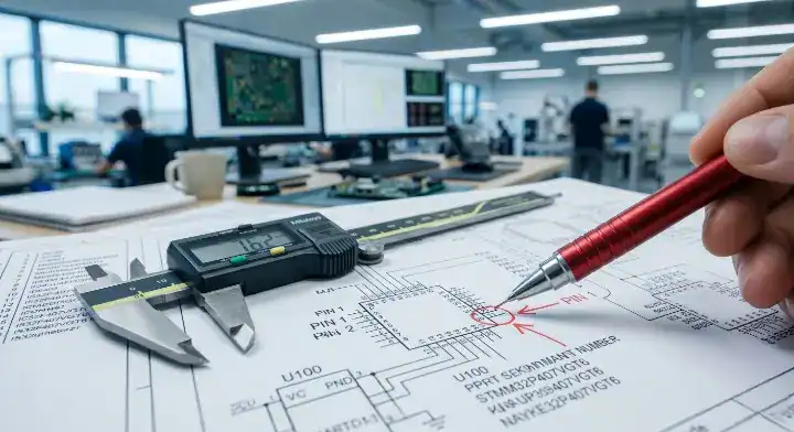
What Makes a Good Assembly Drawing vs. a Useless One?
A good assembly drawing provides clear component placement, explicit polarity marks for diodes, keep-out zones, and board dimensions in a single PDF. Useless drawings lack orientation indicators, causing 15% of first-article inspection failures due to backwards components.
Altium’s PCB documentation guide provides EDA-specific best practices, recommending that you generate manufacturing outputs directly from design tools rather than drawing them manually.
Watch out for these red flags:
- Text overlapping with component pads.
- Missing pin 1 indicators on ICs.
- No physical board dimensions or mounting hole coordinates.
Our engineers use your drawings to verify the automated machine placement. We offer a 99.7% first-pass yield rate because we double-check the physical board against your PDF visually.
Bottom line: Include a high-resolution PDF assembly drawing that clearly marks Pin 1 for every single IC, connector, and diode.
How Do You Write Test Specifications That Your CM Can Actually Execute?
Executable test specifications must list the exact test method, measurable pass/fail criteria (e.g., 3.3V ± 0.1V), physical test point locations, and required sample sizes. Vague instructions like “verify power” lead to custom fixture engineering that costs $500–$2,000.
Testing is not magic. The factory floor needs binary instructions. You must define the exact voltage, current, or signal output expected at specific nodes.
Your test spec must outline:
- Power input requirements (voltage and current limits).
- Expected output values at labeled test points (TP1, TP2).
- Firmware flashing instructions with software links.
- Required test hardware (multimeter, oscilloscope, custom pogo-pin jig).
If you run 5 prototypes, request flying probe testing; if you run 1,000+ units, invest in an ICT fixture to drop your per-board test costs significantly.
Bottom line: Provide a step-by-step PDF document that tells the technician exactly where to put the probes and exactly what numbers mean “Pass”.
What Revision Control Practices Prevent Production Errors?
Strict revision control requires matching the version number across every file in your PCB assembly documentation package and packaging them into a single, date-stamped ZIP file. Mixing v1.8 BOMs with v2.1 Gerbers is the root cause for 30% of wrong-part placements on the SMT line.
Never use file names like board_final_v2_new.zip. This terminology creates chaos on the factory floor. Follow a strict Gerber file guide naming convention.
Use this naming logic:
ProjectName_Assy_Rev1.0.zipProjectName_BOM_Rev1.0.xlsxProjectName_Gerber_Rev1.0.zip
For prototype runs (5–10 boards): simple filename versioning works. For mid-volume production (100–500 boards): implement a formal ECO (Engineering Change Order) document to track exactly what changed between versions.
Bottom line: If you change one trace on the board, you must increment the revision number on all files and submit a completely fresh ZIP folder.
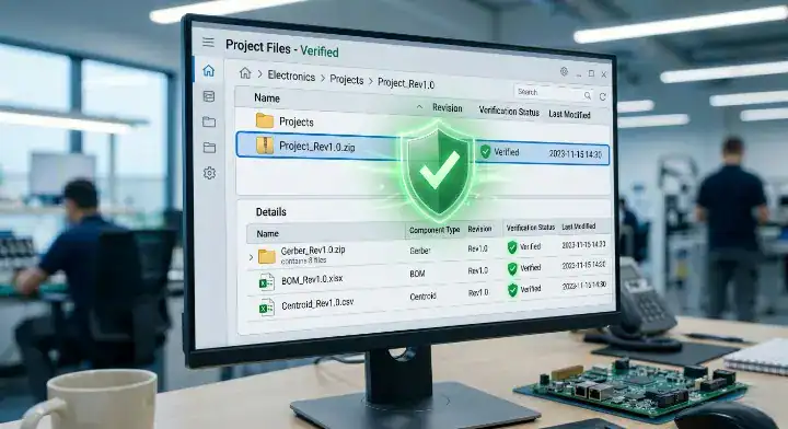
A Complete Documentation Readiness Checklist Before You Submit to Your CM
Passing a documentation readiness checklist ensures your 5 core files are formatted, synced, and verified, dropping your CM’s pre-production setup time from 11 days to 4 days. Missing just one centroid file stops the pick-and-place programming entirely.
You can use a comprehensive PCB assembly RFQ checklist to verify your package before emailing your account manager.
Based on our experience: A medical device client gave us what they called a ‘complete’ documentation package. It had Gerber files, a BOM in PDF format (not editable), and a single-page assembly drawing with no dimensions. They missed the centroid file, fabrication notes, test specification, and any mention of IPC class. We spent 3 days in back-and-forth emails extracting the information we needed. Once we rebuilt their BOM into a proper spreadsheet format and generated the centroid from their Gerber, we found 12 component reference designator mismatches. The client then provided a second revision of the BOM, which introduced 3 new mismatches. After we implemented a strict documentation checklist requirement for all new customers, the average time from file submission to production start dropped from 11 days to just 4 days.
Table 4: Documentation Readiness Checklist
| Item | Check | Expected Status |
|---|---|---|
| BOM | Excel format, exact MPNs | Complete |
| Gerbers | RS-274X, all layers included | Complete |
| Centroid | X/Y, rotation, side data | Complete |
| Revisions | All files match same version | Verified |
| Fab Notes | Material, finish, thickness stated | Complete |
If you pass this checklist, your job hits the SMT floor immediately; if you skip it, expect 3 days of email tennis and delayed shipping.
Bottom line: Run your entire zip folder through this checklist manually before you request a quote from any manufacturer.
Submitting an incomplete file package guarantees delays, extra fees, and endless email chains. By treating your documentation with the same rigor as your schematic design, you eliminate manufacturing friction. QueenEMS provides full turnkey service from component sourcing to final testing. We run a free DFM/DFA engineering review on every order to catch mismatches before they cost you money. Stop losing weeks to documentation errors. Contact us today to submit your verified package and get your boards built right the first time.
FAQs
Can I submit a PDF instead of an Excel BOM? No, you must submit your BOM in an editable Excel or CSV format. Pick-and-place machines and procurement software cannot parse data from a flat PDF, which means the factory must type out your parts manually, causing major delays. Always export a direct spreadsheet from your CAD tool.
How do I know if my centroid file is correct? Yes, you can verify it by checking for four specific data columns: X-axis location, Y-axis location, rotation angle (0, 90, 180, 270), and board side (Top/Bottom). If your file has these four columns mapped to your reference designators, the CM can program their machines instantly. Open your CSV in Excel to double-check these headers.
What is the fastest way to get a turnkey assembly quote? Provide all 5 core files bundled into a single ZIP folder containing 100% matched revision numbers. When you provide exact MPNs and a clean Gerber set, automated quoting systems can process your order within 24 hours. Verify your files against our checklist before uploading.
Written by the QueenEMS Engineering Team
Upload your files today · Free DFM check before production · Ship worldwide
Get your PCB prototypes in as fast as 24 hours. We handle FR4, Rogers, and Flex up to 60 layers — free prototypes for 2–4 layer boards, no minimum order.
Just upload your Gerber + BOM — we source every part, assemble, and inspect (AOI + X‑Ray) so you don't have to chase suppliers. Boards ship in as fast as 24 hours.