
Quick Answer: A centroid file PCB assembly requirement (often called a pick-and-place file) is a machine-readable digital map containing the exact X/Y coordinates, rotation angle, and layer placement for every surface mount component on your board. To program SMT machines without manual delays, your file must include exactly 5 mandatory fields—RefDes, X, Y, Rotation, and Layer—and perfectly align its origin point with your bare board data.
Key takeaways:
- Missing or misaligned centroid files trigger up to 80% of initial SMT programming delays.
- Manual rotation corrections by a contract manufacturer due to IPC-7351 mismatches can cost $50–$150 per file.
- Centroid data must match your BOM row count exactly; 100 placed parts mean 100 rows.
- Generating a new file directly from native CAD software takes less than 2 minutes and prevents costly reverse-engineering.
Table of Contents
- What Is a Centroid File and Why Does Your PCB Assembler Need It?
- What Data Fields Must a Centroid File Contain?
- Centroid File vs BOM vs Gerber: How the Three Assembly Files Work Together?
- How to Generate a Centroid File from KiCad, Altium, and Eagle?
- What Are the Most Common Centroid File Errors That Cause Assembly Failures?
- How to Validate Your Centroid File Before Submitting to Your Manufacturer?
- What Should You Do If You Lost or Cannot Generate a Centroid File?
- What Centroid File Format Does Your Assembly House Actually Need?
- FAQ
You’ve just finished routing a complex 6-layer board, exported your manufacturing data, and sent it off for quoting, only to get an email back asking for the “XY data.” Without a valid centroid file PCB assembly line machines cannot run, and you are suddenly facing a 48-hour delay while the factory tries to guess where your microcontrollers go. After processing 2,400+ assembly orders last year, we know exactly how missing or broken placement data derails hardware schedules. This guide breaks down exactly how to prepare, validate, and troubleshoot the PCB assembly quote files you need to get your boards built on time.
What Is a Centroid File and Why Does Your PCB Assembler Need It?
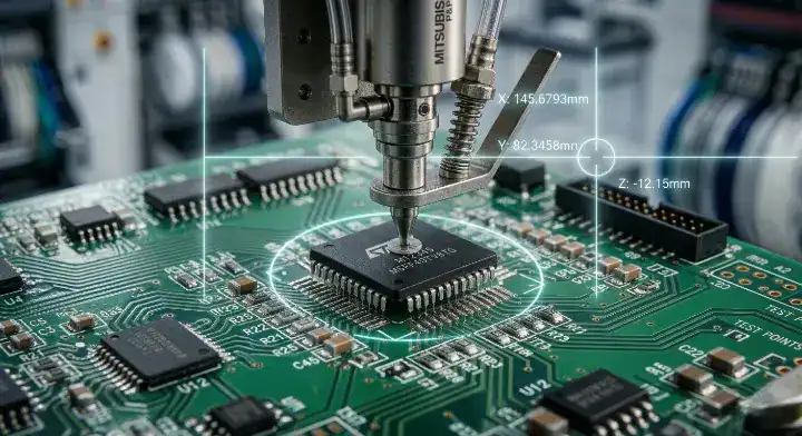
A centroid file is a text-based digital map that dictates the precise physical center (X/Y coordinates) and orientation of every surface-mount component on a circuit board, guiding the robotic nozzles during assembly. Without this specific file, factories must manually teach the pick-and-place machines where every part belongs, extending your setup time by at least 24 to 48 hours.
Engineers refer to this document by many names: pick and place file, XY file, component placement list (CPL), or position file. Despite the different names, they all serve the exact same function. The SMT (Surface Mount Technology) machine reads these coordinates to know exactly how far to travel across the bare board before dropping a resistor or IC onto the wet solder paste.
Now, here’s the part that surprises most customers… Many designers assume the machine figures out placement visually. While high-end machines use cameras to find fiducial marks (copper reference dots on your board) to correct minor physical shifting, the robotic head still needs the raw mathematical coordinates from your centroid file to know the general address of each footprint.
If the origin point (the 0,0 coordinate) of your centroid file does not match the origin point of your bare board design, every single component will be placed off-target by that exact offset distance.
Centroid Terminology and Functions
| Term / Alias | Meaning in Manufacturing | Why Factories Need It |
|---|---|---|
| Pick and Place File | General term for XY data | Programs SMT machine head movement |
| CPL (Component Placement List) | Focuses on the parts being mounted | Cross-references against the BOM |
| XY File | Focuses on the coordinate math | Defines the geometric center of footprints |
| Fiducial Marks | Physical copper dots on the board | Calibrates the physical board to the XY data |
The terminology varies by region and software, but the core requirement remains absolute—factories need coordinate data to automate placement.
Bottom line: Always provide a generated position file with your order; expecting an assembler to place hundreds of components by looking at a PDF drawing guarantees delays and placement errors.
What Data Fields Must a Centroid File Contain?
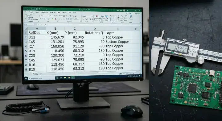
A valid centroid file must contain exactly 5 fundamental data fields for every placed part: Reference Designator (RefDes), X-coordinate, Y-coordinate, Rotation angle, and Board Layer (Top or Bottom). Omitting even one of these 5 columns forces the assembly engineer to halt production, kick the job back to your purchasing team, and wait for new files.
Most CAD software exports 8 to 10 columns by default, including footprint names and component values. While extra data doesn’t hurt, the robotic placement machines only parse the core geometry and identification.
Handling “Do Not Place” (DNP) Components
Engineers frequently ask how to handle parts that are on the schematic but shouldn’t be populated on the current batch. You have two choices. You can completely delete those rows from the CSV file before sending it. Alternatively, you can leave them in but add a “DNP” tag in a dedicated notes column. If you leave a coordinate row active without a DNP note, the machine will stop and throw an error when it cannot find the physical part in the feeder.
Here’s where it gets real… Your X and Y coordinates must represent the geometric center of the physical component body, not pin 1. If your footprint was built with the origin at pin 1 instead of the center, the SMT nozzle will pick up the part off-center, causing uneven placement force and high defect rates.
Required Centroid Data Fields
| Data Field | Description | Example Value | Common Error Consequence |
|---|---|---|---|
| Designator (RefDes) | Matches part to the BOM | R12, U4, C102 | Machine places wrong value part |
| X Coordinate | Horizontal distance from origin | 14.25 (mm) | Part placed completely off the pads |
| Y Coordinate | Vertical distance from origin | 8.50 (mm) | Part placed completely off the pads |
| Rotation | Angle of component (0-360) | 90, 180, 270 | Polarized part placed backward |
| Layer / Side | Top or Bottom of the PCB | Top, T, Bottom, B | Part placed on the wrong side of board |
If your exported file lacks the Layer column, the factory cannot split the job between the top-side and bottom-side SMT runs.
Bottom line: Open your exported file in a spreadsheet editor and verify the 5 mandatory columns exist and contain valid numerical data before emailing it to your manufacturer.
Centroid File vs BOM vs Gerber: How the Three Assembly Files Work Together?
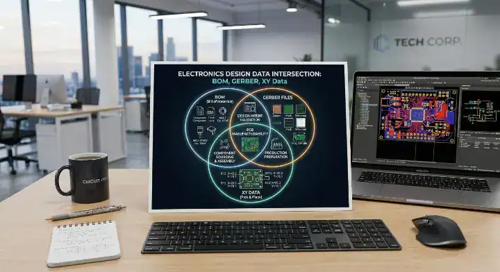
The Gerber file defines the physical copper layout, the BOM for PCB assembly specifies which physical parts to buy, and the centroid file bridges them by telling the SMT machine exactly where to place those purchased parts on the copper. If these three files lack perfect synchronization, your board cannot be assembled successfully.
Hardware startups often view these as three isolated requirements. In reality, they form a strict verification triangle.
Factory Veteran View: The Problem: We regularly see clients submit a BOM with 50 unique reference designators, but their pick-and-place file only contains 48 rows. Our Action: We built an automated parsing script that cross-references the RefDes column in the BOM directly against the RefDes column in the XY file instantly upon upload. The Result: This flags missing coordinates immediately, cutting our average pre-production engineering hold times from 48 hours down to just 2 hours.
The Three-Way Cross Check
The designators in your centroid file must exist in your BOM. The coordinates in your centroid file must fall within the physical board outline defined in your Gerber file guide data. The rotation specified in the XY data must align with the silkscreen polarity marks printed on the physical board.
So what does this actually mean for your workflow? It means you should never update one file without re-exporting the other two. If you change a footprint size in your layout, the centroid center shifts.
Upload your BOM for a free DFM check with our engineering team to see how seamlessly our software aligns your three critical manufacturing files.
The Core Assembly Files Comparison
| File Type | Primary Purpose | Who Uses It | Format |
|---|---|---|---|
| Gerber / ODB++ | Defines copper, solder mask, and silkscreen | PCB Fabricator | RS-274X, .zip |
| Bill of Materials (BOM) | Defines MPNs, values, and quantities | Procurement | .xlsx, .csv |
| Centroid / XY File | Defines placement math and orientation | SMT Programmer | .csv, .txt |
These files must be exported from the same final revision of your CAD project to guarantee perfect alignment.
Bottom line: Treat your BOM, Gerbers, and Centroid as a single, inseparable package; updating one without updating the others is the fastest way to trigger a production hold.
How to Generate a Centroid File from KiCad, Altium, and Eagle?
You can generate a centroid file in under two minutes using the native export functions in your CAD software, typically found under the fabrication or assembly outputs menu. Relying on default software settings is generally safe, provided you select CSV format and explicitly include both top and bottom layers.
Every major EDA tool handles this export slightly differently, but the underlying output remains simple text data.
Exporting from Major CAD Tools
In KiCad, navigate to File > Fabrication Outputs > Component Placement (.pos). Make sure to select “ASCII” format and “Single file for board” to keep top and bottom components in one list. In Altium Designer, go to File > Assembly Outputs > Generates pick and place files. Set the output to CSV and ensure the units (Metric or Imperial) match your Gerber exports. In Autodesk Eagle, you actually run a ULP (User Language Program). Go to File > Run ULP and search for mountsmd.ulp for the top side, and mountsmd-bottom.ulp for the bottom side.
Want the honest answer? The most common mistake during export is changing the origin point right before generating the XY data. Set your auxiliary origin once during board layout and leave it untouched.
CAD Tool Export Reference
| EDA Software | Menu Path / Command | Default Output Format | Key Export Setting to Check |
|---|---|---|---|
| KiCad | Fabrication Outputs > Component Placement | .pos (ASCII) | Use “Single file for board” |
| Altium | Assembly Outputs > Pick and Place Files | .csv or .txt | Set Units to match Gerbers |
| Eagle | Run ULP > mountsmd.ulp | .mnt / .mnb | Must run twice (Top & Bottom) |
| Cadence Allegro | Export > Placement | .txt | Select “Body Center” origin |
Always open the resulting file in a simple text editor immediately after export to verify the data populated correctly.
Bottom line: Master your specific CAD tool’s export path for XY data; it is a fundamental skill that takes seconds to execute but saves days of manufacturing delays.
What Are the Most Common Centroid File Errors That Cause Assembly Failures?
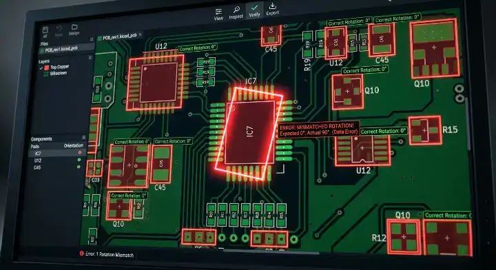
Inconsistent rotation conventions—specifically mismatches between your CAD tool’s default orientation and the IPC-7351 pin 1 standard—cause roughly 60% of all centroid-related assembly failures. When diodes or ICs are placed 90 or 180 degrees off, you face total functional failure and expensive manual rework.
This is a massive pain point across hardware engineering forums. The IPC-7351 standard dictates that for passive components, pin 1 should be on the left (0 degrees). For ICs, pin 1 should be top-left. However, many EDA footprint libraries were built years ago using arbitrary zero-degree orientations.
The Bottom Side Rotation Trap
The confusion multiplies on the bottom layer. When a component moves to the bottom side, some software mirrors the X coordinate and reverses the rotation logic. From a manufacturer’s perspective, we read bottom-side rotation from a “top-down view looking through the board.” If you manually flip or mirror the centroid text file in Excel to “help” the factory, you will completely break the SMT machine’s coordinate math.
Factory Veteran View: The Problem: We received a batch of 500 boards where the CAD default rotation for a critical diode was 180 degrees opposite of the tape-and-reel packaging orientation. Our Action: We strictly enforce a visual 3D overlay check, loading the XY data directly over the Gerber paste layer before any SMT programming begins. The Result: We caught the polarity mismatch before printing any solder paste, preventing a $4,000 scrap event and maintaining our standard 99.7% first-pass yield.
Troubleshooting Component Rotation
| Error Type | Symptom | Root Cause | How to Fix It |
|---|---|---|---|
| Pin 1 Mismatch | IC placed 90° off | CAD library differs from IPC standard | Factory adjusts offset during CAM setup |
| Bottom Layer Flip | Bottom parts placed backward | Manually mirroring the CSV file | Never manually edit bottom layer math |
| Missing Designator | SMT machine skips placement | Parts flagged as DNP incorrectly | Audit DNP list against schematic |
| Origin Offset | Entire board shifts by 2mm | Gerber and XY origins don’t match | Re-export both using same aux origin |
Do not attempt to fix rotation degrees manually in Excel; let the assembly house handle offsets during their CAM engineering phase.
Bottom line: State clearly in your assembly notes if your footprints strictly follow the IPC-7351 zero-orientation standard; if you aren’t sure, instruct the factory to verify polarity against the silkscreen.
How to Validate Your Centroid File Before Submitting to Your Manufacturer?
You can validate your centroid file in less than 60 seconds by cross-checking the total row count against your BOM’s placed component count and verifying the measurement units match your Gerbers exactly. This simple sanity check prevents the top file errors that trigger immediate manufacturing holds.
Assembly files FAQs constantly highlight the same recurring issues: missing designators, designators that don’t exist on the silkscreen, and XY files that are entirely blank. Before you zip your files, you need to run a pre-submission audit.
The 60-Second Validation Audit
First, do a designator count cross-check. If your BOM lists 120 parts to be placed, your centroid file must have exactly 120 rows of coordinate data. Second, check your coordinate boundaries. If your board is 50mm by 50mm, look at the X and Y columns. If you see a coordinate listed as “145.00,” your origin point is floating wildly outside the board area.
But here’s what most guides won’t tell you… The safest way to validate rotation is to use a free online Gerber viewer that supports XY overlay. You upload your copper layers and drop the centroid CSV on top. You will instantly see a visual box overlaying every footprint. If the box is sideways relative to the copper pads, your rotation is wrong.
Get a transparent quote within 24 hours with us, and our engineers will perform this exact validation overlay for you automatically.
Pre-Submission Validation Checklist
| Validation Step | How to Execute | What It Prevents |
|---|---|---|
| Row Count Check | Compare BOM parts to CSV rows | Prevents missing components on the line |
| Unit Consistency | Verify mm vs mils setting | Prevents massive scaling errors at SMT |
| Boundary Check | Scan highest X/Y values | Prevents origin point offset failures |
| Visual Overlay | Load into a free Gerber viewer | Catches 90/180 degree rotation errors |
Taking one minute to run this checklist saves days of back-and-forth emails with CAM engineers.
Bottom line: Never submit a centroid file without first confirming that its row count perfectly matches the quantity of physical parts listed in your BOM.
What Should You Do If You Lost or Cannot Generate a Centroid File?
If you lose your centroid file, your best option is to export a fresh copy from the native CAD design file, which takes mere minutes and costs nothing. If the CAD file is permanently lost, a contract manufacturer can reverse-engineer the XY data directly from your Gerbers, typically charging a $50 to $150 engineering fee.
Engineers migrating old projects to a new manufacturer often realize they only saved the PDFs and Gerbers, losing the native CAD files entirely. This stalls production because SMT machines cannot read PDFs.
Recovery Options and Costs
You have three paths. The first is finding the original .brd or .kicad_pcb file. The second is paying the factory to rebuild it. The third, applicable only to very simple boards (under 20 components), is manually typing the coordinates into Excel by measuring the board with digital calipers—though this is highly prone to human error.
Factory Veteran View: The Problem: Customers attempting to revive legacy DFM PCB design projects frequently submit orders lacking any pick-and-place data. Our Action: We deploy advanced CAM software to calculate the geometric center of surface-mount pads directly from the Gerber paste layer, extracting a new centroid list automatically. The Result: We successfully rebuilt missing XY files for over 300 legacy boards last year, achieving perfect placement without needing the original design files.
Lost Centroid File Recovery Options
| Recovery Method | Time Required | Cost Impact | Accuracy Risk |
|---|---|---|---|
| Re-export from CAD | 2 minutes | $0 | Zero risk |
| Factory CAM Extraction | 24 – 48 hours | $50 – $150 NRE fee | Low (Requires polarity verification) |
| Manual Excel Creation | 2 – 4 hours | Internal labor cost | High risk of manual typos |
To prevent this issue, incorporate your exported CSV files into your Git or internal version control system right alongside your Gerbers.
Bottom line: If you lose your pick-and-place data, do not attempt to measure and type coordinates manually; pay the small engineering fee for the factory to extract it mathematically from the Gerber paste layer.
What Centroid File Format Does Your Assembly House Actually Need?

The universally accepted format for a centroid file is a comma-separated values (.CSV) text file, which allows SMT assembly engineers to easily import, read, and manipulate the data in Excel or native machine software. While some CAD programs export proprietary extensions, converting them to plain CSV guarantees zero compatibility issues.
Factories run various brands of pick-and-place machines—Yamaha, Fuji, Juki, Panasonic. Each machine requires a slightly different proprietary input format. The factory’s CAM engineering team uses specialized software to digest your raw CSV data and spit out the exact machine code required for their specific line.
That said… Do not send PDFs, Word documents, or image files containing your coordinates. The data must be machine-readable text. If you use KiCad, the .pos file is perfectly fine because it is just ASCII text formatted with spaces.
Acceptable Centroid Formats
| File Extension | Format Type | Factory Acceptance | Notes |
|---|---|---|---|
| .CSV | Comma Separated | Universal (Preferred) | Easily edited in Excel |
| .TXT / .PRN | Space/Tab Separated | Universal | Clean, readable ASCII format |
| .POS | KiCad ASCII | Universal | Factory will rename or parse as text |
| .XLSX | Excel Spreadsheet | Widely Accepted | Good, but basic CSV is lighter |
| Document | Rejected | Requires manual data entry; delays job |
Keep the formatting as plain as possible; stripping out extra headers or logo text at the top of your CSV makes the factory’s automated parsing tools run much smoother.
Bottom line: Always export your XY coordinate data as a simple .CSV file to guarantee immediate processing by any contract manufacturer globally.
Preparing your manufacturing data correctly shouldn’t require guesswork—now you know exactly how to align your BOM, Gerbers, and pick-and-place files to prevent costly setup delays. At QueenEMS, we offer full turnkey services with completely transparent pricing, providing a free DFM/DFA engineering review on every single order. With our 3D AOI and X-Ray inspection standard on every BGA joint, you achieve a 99.7% first-pass yield rate that scales seamlessly from prototype to mass production. We believe every hardware team deserves a manufacturing partner who explains their processes, not hides them. Contact us today to get your board files reviewed and quoted accurately.
Written by the QueenEMS Engineering Team
FAQ
1.Can the factory build my board if I only send Gerber files and a BOM? It depends, but usually yes, for an extra fee. If you only provide Gerbers, the CAM engineers must spend hours reverse-engineering the copper pads to extract the geometric centers and create a new centroid file from scratch. This typically adds $50 to $150 to your setup costs and delays production by 1 to 2 days. Request a free first-article inspection on your first order to see how we handle your data.
2.Do I need to include through-hole (THT) components in my centroid file? No, you do not strictly need to include THT parts. Pick-and-place machines are designed exclusively for surface mount technology (SMT). Through-hole parts are typically inserted manually or by specialized wave soldering equipment that does not rely on precise XY coordinate files. Upload your BOM for a free DFM check, and we will sort your SMT and THT requirements automatically.
3.What should I do if my top and bottom components export into two separate centroid files? That is perfectly acceptable. You can submit them as two separate files (e.g., placement_top.csv and placement_bottom.csv). The factory’s CAM software will easily process them as distinct runs for the top and bottom SMT passes. You do not need to manually merge them into a single spreadsheet. Get a transparent quote within 24 hours to see how quickly we process multi-layer assemblies.
Upload your files today · Free DFM check before production · Ship worldwide
Get your PCB prototypes in as fast as 24 hours. We handle FR4, Rogers, and Flex up to 60 layers — free prototypes for 2–4 layer boards, no minimum order.
Just upload your Gerber + BOM — we source every part, assemble, and inspect (AOI + X‑Ray) so you don't have to chase suppliers. Boards ship in as fast as 24 hours.