
Quick Answer: A standard FR4 prototype costs $1–$5 per board, while an Al2O3 ceramic PCB costs $15–$50, and a high-end AlN board reaches $80–$200+. You only need a ceramic substrate when operating temperatures exceed 150°C, thermal conductivity requirements surpass 20 W/m·K, or you are directly bonding bare silicon chips.
Key takeaways:
- FR4 thermal conductivity maxes out at 0.3–0.4 W/m·K, whereas AlN ceramic reaches 170–230 W/m·K.
- Ceramic PCBs handle extreme temperatures up to 350–600°C, compared to the FR4 limit of 130–150°C.
- Standard FR4 prototypes take 3–5 days to manufacture, while ceramic boards require 7–15 days due to high-temperature firing processes.
- High-Tg FR4 with thermal vias remains the most cost-effective choice for 90% of designs operating under 5W/cm² power dissipation.
Table of Contents
- What Is the Core Difference Between Ceramic PCB and FR4?
- How Does Thermal Conductivity Compare Between Ceramic and FR4 Substrates?
- When Does FR4 Actually Outperform Ceramic PCB?
- How Much More Does a Ceramic PCB Cost Than FR4?
- Which Ceramic Material Should You Choose: Al2O3, AlN, or Si3N4?
- What Applications Require Ceramic PCB Over FR4?
- Can You Use Metal Core PCB (MCPCB) Instead of Ceramic?
- How to Decide: Ceramic PCB vs FR4 Decision Flowchart?
- FAQ
You are designing a high-power module and wondering if standard FR4 will survive the thermal load. Upgrading to a ceramic substrate fixes the heat issues immediately, but it destroys your project budget with a massive price jump. Based on our 99.7% first-pass yield rate data across thousands of orders at QueenEMS, evaluating ceramic PCB vs FR4 requires hard numbers, not guesses. If you select the wrong material early on, you risk either field failures from overheating or wasting thousands of dollars on an over-engineered board.
In this guide, a seasoned ceramic PCB manufacturer breaks down the exact scenarios where paying the ceramic premium makes financial sense.
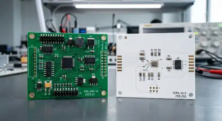
What Is the Core Difference Between Ceramic PCB and FR4?
The core difference between a ceramic PCB and FR4 is the base material construction; FR4 relies on woven fiberglass bound with epoxy resin, while a ceramic PCB uses solid inorganic compounds like Al2O3 or AlN bonded directly with copper. Because of this structural difference, ceramic boards are 60 to 575 times more thermally conductive than standard FR4 material.
To understand how these materials dictate your manufacturing process, look at how they are built:
- FR4 Manufacturing: Uses standard lamination pressing prepreg and copper foil together.
- Ceramic Manufacturing: Uses DBC (Direct Bonded Copper), DPC (Direct Plated Copper), or AMB (Active Metal Brazing) combined with doctor blade tape casting, followed by firing at extreme temperatures between 850°C and 1700°C.
- Layer Limits: FR4 easily scales to 40+ layers, whereas ceramic is generally restricted to 1-4 layers unless you pay exponentially higher costs for LTCC/HTCC processes.
Here is the reality:
| Feature | FR4 Substrate | Ceramic Substrate (Al2O3 / AlN) |
|---|---|---|
| Material Base | Epoxy resin + woven fiberglass | Inorganic ceramic compounds |
| Thermal Conductivity | 0.3 – 0.4 W/m·K | 24 – 230 W/m·K |
| Max Operating Temp | 130°C – 150°C | 350°C – 600°C |
| Water Absorption | 0.15%+ | 0% (Hermetically sealed) |
| Mechanical Traits | Flexible, lower dimensional stability | Highly rigid, exceptional stability, brittle |
Choose FR4 for standard digital circuits operating in normal ambient environments. Choose ceramic when you need zero water absorption and total dimensional stability at temperatures exceeding 150°C.
Bottom line: Stick to FR4 for 90% of your standard designs, but switch to a ceramic PCB material when thermal accumulation becomes the primary cause of your component failures.
How Does Thermal Conductivity Compare Between Ceramic and FR4 Substrates?
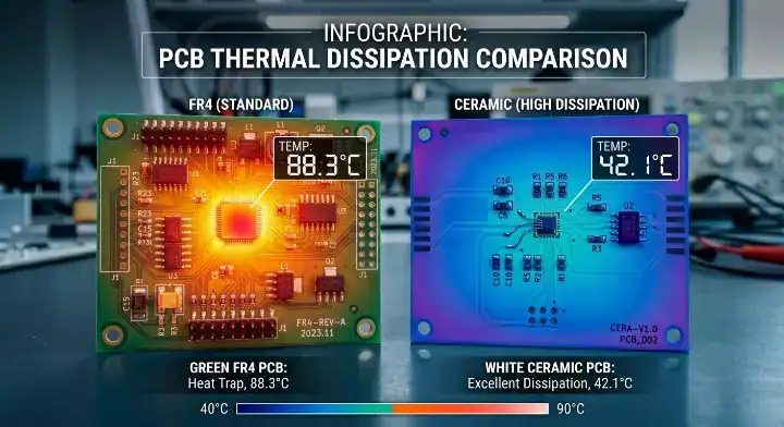
FR4 thermal conductivity maxes out at 0.3 to 0.4 W/m·K, whereas Al2O3 provides 24 to 28 W/m·K, and AlN delivers a staggering 170 to 230 W/m·K. This means a bare ceramic board transfers heat up to 575 times faster than FR4, removing the need for complex arrays of thermal vias or heavy external heatsinks.
Heat dissipation is not the only thermal metric that matters. CTE (Coefficient of Thermal Expansion) is the rate at which a material expands when heated. FR4 has a CTE of 13-15 ppm/°C, while ceramic boards sit at 4.5-7.5 ppm/°C, closely matching a silicon chip’s 2.6 ppm/°C.
Think about it this way:
- If you mount a bare silicon die directly to FR4, the difference in expansion rates during thermal cycling will shear the solder joints apart.
- Using ceramic eliminates this mechanical stress because the substrate expands at roughly the same rate as the silicon component.
- Standard FR4 material properties simply cannot support bare-die attachments in high-power applications without severe reliability risks.
Bottom line: Use FR4 with thermal vias for low-power heat management, but specify ceramic immediately when your power dissipation exceeds 5W/cm² or you are using direct-bonded silicon components.
When Does FR4 Actually Outperform Ceramic PCB?
FR4 genuinely outperforms ceramic PCBs when you need multilayer high-density routing (over 4 layers), high-volume consumer electronics pricing under $5 per board, or fast prototyping delivery in 3 to 5 days. Many engineers get pushed toward ceramic by sales teams, only to realize their budget is ruined and lead times are doubled for performance they never needed.
We see this mistake often. A client requested Al2O3 for a smart home device because they worried about a 1W LED array. We switched them to High-Tg FR4. We saved them 65% on unit costs while keeping junction temperatures well within safe limits.
Here are the 5 specific scenarios where FR4 is the strictly superior choice:
- Multilayer High-Density Routing: FR4 supports 40+ layers easily. Ceramic is cost-prohibitive beyond 4 layers.
- Large Batch Consumer Electronics: When per-unit cost is the defining metric, FR4 wins every time.
- Fast Prototyping: FR4 takes 3-5 days. Ceramic takes 7-15 days due to specialized tooling and firing.
- Moderate Operating Temperatures: If your board stays under 130°C, High-Tg (170-180°C) FR4 is a perfectly safe, cost-effective alternative.
- High Vibration Environments: Ceramic is rigid but brittle, making it susceptible to fractures under mechanical shock. FR4 absorbs vibration much better.
What does this mean for you?
Bottom line: Do not over-engineer your product; stick to High-Tg FR4 if your operating temperature stays below 130°C, your layer count is high, and you operate in a high-vibration environment.
How Much More Does a Ceramic PCB Cost Than FR4?
A standard FR4 prototype costs $1 to $5 per board, while an Al2O3 ceramic PCB costs $15 to $50, and a high-end AlN board runs $80 to $200+ per piece. At mass production volumes, the ceramic volume discount is smaller because the raw material cost accounts for a much higher percentage of the final price.
Engineers constantly ask exactly how much the price gap shrinks at scale. Because ceramic NRE (Non-Recurring Engineering) and tooling costs are higher, the gap remains significant regardless of volume.
| Material Type | Prototype Cost (5-10 boards) | Mid-Volume Cost (100-500 boards) | High-Volume Cost (1,000+ boards) |
|---|---|---|---|
| Standard FR4 | $1 – $5 / pc | $0.50 – $2 / pc | $0.20 – $1 / pc |
| Al2O3 (Alumina) | $15 – $50 / pc | $8 – $20 / pc | $5 – $12 / pc |
| AlN (Aluminum Nitride) | $80 – $200+ / pc | $40 – $100 / pc | $25 – $70 / pc |
Choose FR4 for disposable or low-margin consumer devices where every cent counts. Choose Al2O3 or AlN when building high-value equipment where a $50 board prevents a $5,000 system failure.
Let’s look at the numbers: For prototype runs (5–10 boards): Expect a 10x to 20x price difference between FR4 and ceramic. For high-volume production (1,000+ boards): Expect a 5x to 8x price difference.
However, you must calculate the Total Cost of Ownership (TCO). If an FR4 board used in an aerospace sensor has a field failure rate 4 times higher than a ceramic board, the replacement and warranty costs make FR4 the more expensive option over a 5-year lifespan.
Bottom line: Ceramic has a drastically higher upfront unit cost, but its TCO becomes lower than FR4 when operating in high-reliability industrial applications where field failures destroy your profit margins.
Which Ceramic Material Should You Choose: Al2O3, AlN, or Si3N4?
Al2O3 (Alumina) is the standard ceramic material used in 80% of applications, offering 24-28 W/m·K at the most economical price point. AlN (Aluminum Nitride) jumps to 170-230 W/m·K for extreme heat loads, while Si3N4 (Silicon Nitride) provides the highest mechanical fracture toughness for heavy automotive environments.
If you decide to move away from FR4, selecting the right inorganic compound dictates your final performance.
| Material | Thermal Conductivity | Cost Tier | Best Application |
|---|---|---|---|
| Al2O3 (Alumina) | 24 – 28 W/m·K | $$ | General power modules, standard LEDs |
| AlN (Aluminum Nitride) | 170 – 230 W/m·K | IGBTs, extreme high-power lasers | |
| Si3N4 (Silicon Nitride) | 80 – 90 W/m·K | $ | High mechanical stress, automotive inverters |
| BeO (Beryllium Oxide) | 250+ W/m·K | $$ | Aerospace (Note: Highly toxic dust, restricted) |
Choose Al2O3 as your default starting point for budget-friendly thermal management. Choose AlN only when your thermal simulation proves Al2O3 cannot handle the heat load.
Why does this matter? Dielectric properties also play a huge role. Ceramic Dk values sit between 6 and 10, compared to FR4’s 4.2 to 4.8. Certain ceramics suffer from dispersion issues at high frequencies; for example, Boron Nitride (BN) shifts to a Dk of 4.5 at 9GHz. If you are building high-frequency equipment, consult your RF PCB manufacturer to match the exact material to your signal integrity requirements.
Bottom line: Default to Al2O3 to keep your project costs down, upgrading to AlN only when your thermal simulation explicitly demands extreme conductivity.
What Applications Require Ceramic PCB Over FR4?
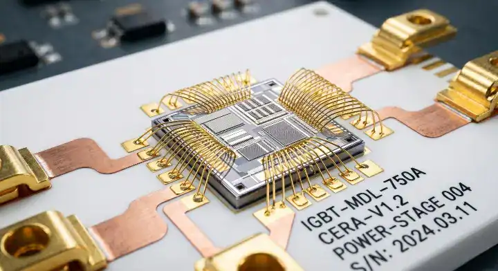
You must use a ceramic PCB over FR4 when designing high-power LED arrays, IGBT power modules, aerospace components facing 350°C+ environments, or optical transceivers. Standard FR4 will simply delaminate, warp, or melt under these specific thermal and environmental stresses.
The decision is rarely ambiguous in certain industries.
| Industry / Application | Recommended Material | Why? | Cost Tier |
|---|---|---|---|
| Consumer Electronics | FR4 | Lowest cost, high layer counts | $ |
| Automotive LED Lighting | MCPCB or Al2O3 | Good thermal transfer, low cost | $$ |
| IGBT Power Modules | AlN Ceramic | Perfect CTE match for bare die, extreme heat | |
| RF / 5G Antennas | specialized FR4 or Ceramic | Stable Dk at high frequencies | $$$ |
| Medical Lasers | AlN Ceramic | Zero thermal expansion tolerance |
Choose FR4 for basic processing and logic boards. Choose ceramic for the specific sub-modules that handle massive voltage conversion or direct laser emission.
The truth is: If your application involves hermetic sealing requirements (0% water absorption) or operating environments continuously above 150°C, you have no choice.
Bottom line: If your product requires bare silicon die attachment or operates in extreme thermal environments above 150°C, ceramic is not an optional upgrade—it is a strict mechanical requirement.
Can You Use Metal Core PCB (MCPCB) Instead of Ceramic?
You can use an MCPCB instead of a ceramic PCB for standard LED lighting and simple motor drivers, but an MCPCB’s dielectric layer creates a severe thermal bottleneck with a conductivity of only 1 to 4 W/m·K. Ceramic PCBs use direct-bonded copper with no dielectric layer, providing a minimum of 24 W/m·K continuous thermal transfer.
Engineers frequently confuse MCPCBs with ceramics, assuming they are cheaper alternatives with identical performance. They are not. The thermal path in an MCPCB must travel through an insulating dielectric layer before hitting the aluminum backing. This layer chokes the heat transfer.
| Feature | FR4 | MCPCB (Metal Core) | Ceramic (Al2O3) |
|---|---|---|---|
| Thermal Bottleneck | Epoxy Resin | Dielectric Layer | None (Direct bonded) |
| Thermal Conductivity | 0.3 – 0.4 W/m·K | 1 – 4 W/m·K | 24+ W/m·K |
| Ideal For | Digital logic | LED arrays, street lights | IGBTs, lasers, bare die |
Choose MCPCB for cost-effective heat sinking in commercial lighting fixtures. Choose a metal core PCB manufacturer who can provide premium dielectric materials if you push the limits of aluminum.
Here is the catch: A customer building an electric vehicle charger attempted to use an aluminum MCPCB to cool an IGBT module to save money. The dielectric layer failed under the voltage and heat stress within 48 hours. We redesigned the module using an AlN ceramic board, instantly resolving the thermal bottleneck and passing strict automotive lifecycle tests.
Bottom line: Never use an MCPCB for bare die attachment or extreme high-voltage power modules; reserve it specifically for cost-sensitive LED applications.
How to Decide: Ceramic PCB vs FR4 Decision Flowchart?
To decide between a ceramic PCB and FR4, use this rule: if your operating temperature is >150°C or power dissipation >5W/cm², choose ceramic. If your budget is <$5 per board, you need >4 routing layers, or your design operates under normal ambient temperatures, stick with FR4.
Follow this logic tree before requesting a quote:
- Step 1: Check Temperature. Is the continuous operating temperature above 150°C? If yes, select Ceramic. If no, proceed to Step 2.
- Step 2: Check Power Density. Is the component power dissipation greater than 5W/cm²? If yes, select Ceramic. If no, proceed to Step 3.
- Step 3: Check Component Type. Are you directly bonding bare silicon chips (die attachment) and require exact CTE matching? If yes, select Ceramic. If no, proceed to Step 4.
- Step 4: Check Layer Count & Budget. Do you need more than 4 routing layers or have a strict budget under $5 per board? If yes, select High-Tg FR4 or MCPCB.
To make it simple: If you fail the extreme thermal and mechanical checks in steps 1 through 3, you are building a standard circuit.
Bottom line: Run your thermal simulation software first; if High-Tg FR4 with standard thermal vias keeps your junction temperature safe, do not pay the massive ceramic premium.
Choosing the right substrate determines whether your product succeeds in the field or fails catastrophically under thermal stress. While ceramic offers unmatched heat dissipation and stability, FR4 remains the undefeated champion of cost-effective, high-density routing.
At QueenEMS, we do not blindly upsell expensive materials. We run a free DFM/DFA engineering review on every order to verify your material choice aligns perfectly with your budget and thermal requirements. With our 99.7% first-pass yield rate and capabilities spanning from simple FR4 prototypes to advanced AlN ceramic modules, we build exactly what your product needs to survive.
Ready to stop guessing about your thermal management? Contact our engineering team today for a data-driven material review and a rapid quote.
Written by the QueenEMS Engineering Team
FAQs
Does a ceramic PCB break easier than an FR4 board? Yes, ceramic PCBs are highly brittle and susceptible to fracture under mechanical shock or bending. You must handle them with specialized equipment during assembly, whereas FR4 is flexible and easily absorbs standard vibrations.
Can I get a ceramic PCB manufactured in 3 days? No, rapid 3-day turnarounds are practically impossible for ceramic boards due to the 850°C to 1700°C firing process and specialized direct copper bonding. Standard quick-turn for ceramic is 7 to 15 days, so plan your prototyping schedule accordingly.
Is High-Tg FR4 a valid replacement for a ceramic substrate? It depends on your operating temperature; High-Tg FR4 handles up to 170–180°C and works perfectly for moderate power applications, but it cannot replace ceramic if you need thermal conductivity above 0.5 W/m·K or exact CTE matching for silicon dies. Evaluate your thermal simulation before making the switch.
Why shouldn’t I just use MCPCB instead of Alumina for my power module? Because the dielectric layer inside an MCPCB limits thermal conductivity to 1–4 W/m·K, which creates a severe bottleneck for concentrated heat sources like IGBTs. Upgrade to Alumina (Al2O3) to achieve a continuous 24 W/m·K thermal path with zero insulating barriers.
Upload your files today · Free DFM check before production · Ship worldwide
Get your PCB prototypes in as fast as 24 hours. We handle FR4, Rogers, and Flex up to 60 layers — free prototypes for 2–4 layer boards, no minimum order.
Just upload your Gerber + BOM — we source every part, assemble, and inspect (AOI + X‑Ray) so you don't have to chase suppliers. Boards ship in as fast as 24 hours.