
Quick Answer: Through-hole PCB assembly delivers reliable mechanical bonds by securing component leads through the entire thickness of a printed circuit board. For high-power and harsh environment applications, THT joints withstand over 50A of current and extreme -55°C to 125°C thermal cycling. Production facilities achieve up to 3,000 components per hour using automated wave soldering while maintaining IPC Class 3 minimum 75% barrel fill requirements. Key takeaways:
- Through-hole joints form structural bonds across multiple board layers.
- Selective soldering processes protect adjacent SMT components on mixed boards.
- THT reduces setup costs for prototype batches under 500 units.
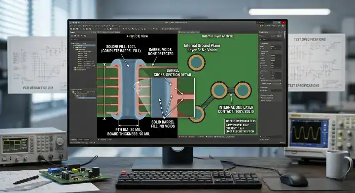
- X-ray inspection is required to verify internal barrel fill percentages.
Table of Contents
- What Makes Through-Hole PCB Assembly Mechanically Superior?
- Why Do THT Joints Excel in High-Power Electronics?
- How Does Through-Hole Tech Handle Harsh Environments?
- How Does Mixed Assembly Combine Through-Hole and SMT?
- Wave vs Selective Soldering for Plated Through-Holes?
- How to Design PCBs for Optimal THT Assembly?
- Is Through-Hole PCB Assembly Still Cost-Effective?
- What IPC Standards Govern Through-Hole Solder Joints?
- Why Is THT Manufacturing Ideal for Rapid Prototyping?
- How to Choose the Right Through-Hole PCB Assembly Partner?
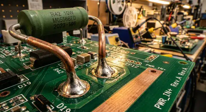
You design a rugged industrial control unit that must survive daily vibration and thermal shock. Surface mount components shear off the board when physical stress exceeds their minimal surface adhesion strength. By implementing professional THT PCB assembly services, you anchor component leads through the entire board thickness, eliminating catastrophic mechanical failures in the field.
What Makes Through-Hole PCB Assembly Mechanically Superior?
Through-hole PCB assembly achieves mechanical superiority by creating physical bonds through the entire Z-axis of the circuit board. This specific structural geometry delivers 10× stronger joint strength compared to surface adhesion alone.
How Do Mechanical Bonds Form?
- Molten solder flows into the plated hole via capillary action.
- The solder creates a solid metal cylinder bonding the component lead to the internal copper barrel.
- Top and bottom fillets form a rivet-like structure holding the pin securely.
Here is the reality: Surface-mount components rely solely on a thin layer of solder paste on a flat pad. A sharp physical impact easily breaks this surface tension, resulting in a disconnected circuit. Through-hole pins distribute mechanical stress across multiple internal board layers, which means the PCB substrate will snap before the joint fails.
Key Takeaway
Through-hole connectors, switches, and large power components require physical anchoring that only through-hole technology provides.
Bottom line: Always specify through-hole components for interfaces subjected to repeated physical insertion cycles.
| Feature | Surface Mount (SMT) | Through-Hole (THT) |
|---|---|---|
| Mechanical Anchor | Surface pad only | Full board thickness |
| Stress Distribution | High localized stress | Distributed across layers |
| Shear Strength | Low | Extremely High |
THT’s physical structure acts as an internal rivet to prevent board-level component shearing.
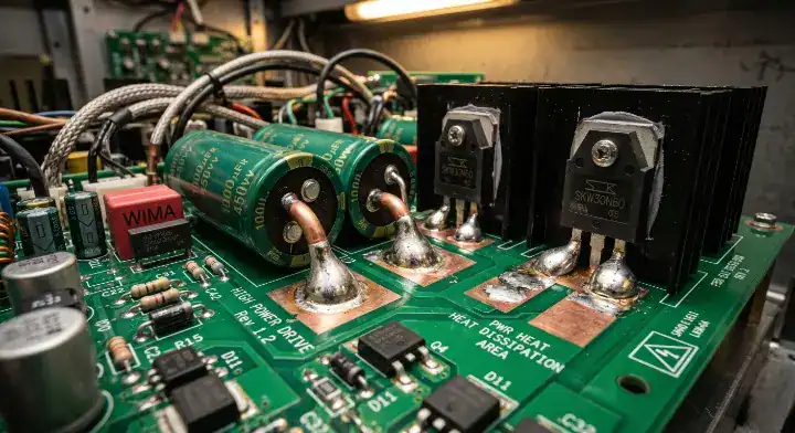
Why Do THT Joints Excel in High-Power Electronics?
THT joints excel in high-power applications because they establish massive conductive pathways capable of handling 50A+ current loads. A standard THT assembly easily outperforms SMT alternatives when routing extreme voltages across a circuit.
Current Capacity Dynamics
- THT leads feature larger cross-sectional areas for electron flow.
- The solid metal barrel acts as a thermal conduit to dissipate heat.
- Multiple internal ground planes can connect directly to the through-hole pin.
Consider this fact: High-current operation generates severe heat that melts standard surface-mount joints. Through-hole leads transfer thermal energy away from the component package, pushing heat through the internal copper layers of the board. This thermal dissipation keeps your power MOSFETs and relays operating safely below their maximum temperature thresholds.
Key Takeaway
You cannot rely on surface pads to transfer 50 amps of current without experiencing thermal degradation over time.
Bottom line: Route all primary power inputs and heavy current loads through dedicated THT pins to prevent thermal failure.
| Metric | SMT Power Pad | THT Power Pin |
|---|---|---|
| Max Current | Limited (~10-15A) | High (50A+) |
| Thermal Dissipation | Poor (Surface only) | Excellent (Multi-layer) |
| Component Size | Constrained | Unrestricted |
High-voltage electronics require the heavy copper mass of a THT joint to safely manage thermal output.
How Does Through-Hole Tech Handle Harsh Environments?
Through-hole tech handles harsh environments by locking components into a rigid structural matrix that resists extreme vibration and temperature fluctuations. A ruggedized mixed technology assembly relies on THT for every high-stress interface.
Real-World Field Endurance
A European agricultural sensor company experienced a 15% connector failure rate within 6 months due to vibration in tractor-mounted enclosures. The root cause was inadequate barrel fill, measured at only 40-50% on their returned units. We redesigned the process with optimized preheating at 105°C topside and implemented 100% X-ray inspection on all joints. Every board shipped with verified 85%+ barrel fill, resulting in a 0% failure rate after 12 months across 800 units.
The solution is direct: Military and aerospace standards, such as MIL-STD-810, demand reliability from -55°C to 125°C with a failure rate of 0.01% over 10 years. SMT joints crack under these repeated thermal expansion cycles. THT pins flex slightly within the heavy solder barrel, absorbing the kinetic energy that causes rigid surface joints to fracture.
Key Takeaway
Field repair and component replacement in remote locations remain significantly easier with THT components.
Bottom line: Use THT assembly for any product deployed in automotive, aerospace, or heavy industrial environments.
| Environment Factor | SMT Vulnerability | THT Solution |
|---|---|---|
| Heavy Vibration | Solder pad fractures | Lead absorbs shock |
| Thermal Cycling | Joint shearing | Z-axis expansion tolerance |
| Field Maintenance | Requires hot air station | Standard soldering iron |
Mechanical stability in extreme temperature zones dictates the use of through-hole anchoring.
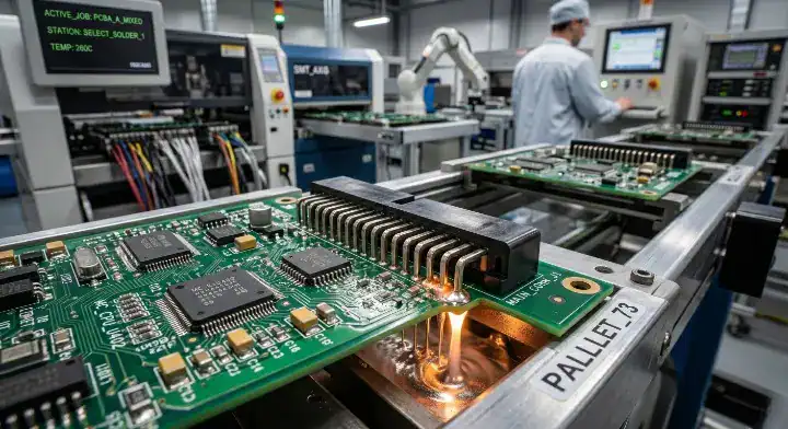
How Does Mixed Assembly Combine Through-Hole and SMT?
Mixed technology assembly combines through-hole and SMT by executing a precise, sequential heating process that prevents cross-contamination. SMT components are reflowed first, and then THT assembly secures the remaining heavy components.
Protecting Surface Mount Parts
- SMT components undergo standard solder paste printing and oven reflow.
- Specialized pallets mask the SMT components on the bottom side.
- Wave or selective soldering processes only target the exposed THT leads.
How do you prevent SMT components from being damaged during wave soldering of THT parts on a mixed board? You control the preheat temperature strictly between 100-110°C topside to prevent thermal shock. Custom titanium pallets shield the delicate SMT packages from the molten solder wave, exposing only the through-hole pins to the required heat.
Key Takeaway
Mixed technology assembly is the standard for modern complex products, balancing SMT density with THT durability.
Bottom line: Always sequence your assembly line to run SMT reflow before exposing the board to any THT wave process.
| Assembly Step | Process | Component Type |
|---|---|---|
| Step 1 | Solder Paste + Reflow | Logic, ICs, Micro-components |
| Step 2 | Masking / Palletizing | Protect bottom-side SMT |
| Step 3 | Wave / Selective Solder | Power, Connectors, Relays |
Proper process sequencing prevents thermal damage to sensitive logic chips during heavy-duty soldering.
Wave vs Selective Soldering for Plated Through-Holes?
Selective soldering targets individual pins using a miniature fountain of solder, whereas wave soldering runs the entire board over a wide molten crest. Efficient wave soldering and selective soldering processes depend entirely on your board layout.
Precision vs Volume Manufacturing
In our selective soldering line, a medical device client sent a 6-layer board with 12 THT power connectors surrounded by 0402 SMT capacitors spaced just 1.5mm away. Using a standard 6mm nozzle resulted in an 8% bridging rate. We switched to a 3.5mm nozzle, adjusted the nitrogen flow to 0.8 L/min, and tuned contact time to 3.2 seconds per pin. The bridging rate dropped to 0.1%, and we maintained 100% barrel fill across a 2,000-board production run.
Consider this data: The selective soldering equipment market reached approximately $75 million in 2024 and is projected to grow at an 8.6% CAGR through 2031, reflecting the demand for precision in mixed assemblies (SMTA). Wave soldering enables high-volume production for boards with predominantly THT parts, processing hundreds of joints in seconds.
Key Takeaway
Selective soldering applies heat only to target pins, physically protecting adjacent SMT parts from thermal stress without requiring custom pallets.
Bottom line: Choose selective soldering for densely populated mixed boards and wave soldering for legacy or power-dominant boards.
| Process Type | Best For | Cycle Time |
|---|---|---|
| Wave Soldering | High volume, THT heavy | Fast (Whole board at once) |
| Selective Soldering | Mixed boards, High density | Moderate (Pin by pin) |
| Hand Soldering | Prototypes, Low volume | Slow (Manual process) |
Equipment selection dictates your production speed and upfront tooling costs for custom pallets.
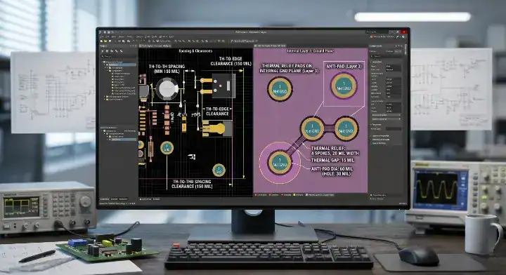
How to Design PCBs for Optimal THT Assembly?
You design PCBs for optimal THT assembly by precisely calculating hole diameters, component orientation, and thermal reliefs. Proper DFM engineering ensures that molten solder easily flows into the plated hole during the manufacturing stage.
DFM Clearance Guidelines
- Align polarized components in the same direction to speed up insertion.
- Maintain a minimum of 2.5mm spacing between THT pads to prevent bridging.
- Apply thermal reliefs to pins connected to large internal ground planes.
The clearance math is strict: IPC-2221 general PCB design standard recommends a lead-to-hole clearance of 0.2mm to 0.25mm for optimal solder flow and reliable joint formation in plated connections (IPC). If your hole is too tight, outgassing traps flux and creates internal voids. If the hole is too wide, the solder falls through without creating a solid mechanical fillet.
Key Takeaway
Component orientation directly impacts the yield rate when a board passes over a solder wave.
Bottom line: Orient all through-hole dual-in-line packages (DIPs) parallel to the direction of the solder wave to prevent trailing edge bridging.
| Design Element | Recommended Value | Consequence of Error |
|---|---|---|
| Lead-to-Hole Gap | 0.2mm – 0.25mm | Voids or poor capillary action |
| Component Spacing | > 2.5mm | Solder bridging between pins |
| Ground Connections | Thermal Relief Pad | Cold solder joints |
Strict adherence to dimensional clearances guarantees structural integrity and prevents costly rework.
Is Through-Hole PCB Assembly Still Cost-Effective?
Through-hole PCB assembly remains highly cost-effective for specific industrial sectors and low-volume production runs. Pairing THT with efficient SMT assembly capabilities optimizes your total manufacturing expenditure.
Break-Even Manufacturing Analysis
When does through-hole actually save money compared to all-SMT designs? THT saves on setup costs for small batches because you avoid expensive solder paste stencils and complex pick-and-place programming. Furthermore, THT components for heavy power applications often cost significantly less than their equivalent surface-mount packages.
Here is the financial reality: Total manufacturing cost must include your product’s field failure rate. THT’s lower failure rate under extreme stress heavily reduces your warranty and recall costs over a five-year lifecycle. The break-even point sits around 500 units; above this volume, all-SMT designs become cheaper due to automated placement speeds.
Key Takeaway
Cost-effectiveness relies on evaluating the entire product lifecycle rather than just the bare board assembly invoice.
Bottom line: Retain THT designs for industrial products running batches under 500 units to bypass heavy SMT setup fees.
| Production Volume | THT Setup Cost | SMT Setup Cost | Recommended Tech |
|---|---|---|---|
| < 500 Units | Low | High (Stencils/Programming) | THT / Mixed |
| 500 – 5000 Units | Moderate | Moderate | Mixed Assembly |
| > 5000 Units | High (Labor/Time) | Low (Highly Automated) | Full SMT (if possible) |
Low-volume industrial electronics benefit financially from the rapid setup times of manual or semi-automated THT insertion.
What IPC Standards Govern Through-Hole Solder Joints?
IPC standards govern through-hole solder joints by defining exact volumetric fill percentages and visual wetting criteria. A compliant THT assembly guarantees that your electronic device will function safely under heavy electrical loads.
Quality Validation Requirements
- Inspect topside fillets to ensure proper capillary action occurred.
- Verify that wetting is evident around 270° of the lead circumference.
- Use 3D X-ray systems to measure internal voiding percentages.
What barrel fill percentage is actually required by IPC for production boards? IPC-A-610 and J-STD-001 specify that Class 2 and Class 3 through-hole assemblies require a minimum 75% barrel fill on the component side for high-reliability applications (IPC).
Engineering Quality Control
A client designing EV charging stations assumed visual inspection was enough, resulting in hidden internal voids on heavy copper boards. We implemented full 3D X-ray inspection on every high-current pin, revealing that standard wave profiles left 30% of the barrel empty inside the inner layers. We adjusted the flux volume and extended the wave dwell time, achieving a consistent 90% fill rate and zero thermal failures.
Key Takeaway
Non-destructive X-ray inspection is the only method to verify internal barrel fill percentages accurately.
Bottom line: Mandate X-ray inspection reports for all Class 3 high-current THT joints to prevent field thermal runaway.
| IPC Standard Class | Minimum Barrel Fill | Wetting Requirement |
|---|---|---|
| Class 1 (General) | Not specified | Basic adhesion |
| Class 2 (Dedicated) | 75% | 180° minimum |
| Class 3 (High-Reliability) | 75% | 270° minimum |
Verifying internal volume parameters eliminates the risk of hidden structural defects in critical systems.
Why Is THT Manufacturing Ideal for Rapid Prototyping?
THT manufacturing accelerates rapid prototyping because engineers can manually modify circuits instantly without specialized rework equipment. Prototyping with through-hole components allows you to test raw concepts before committing to expensive SMT tooling.
Laboratory Testing Advantages
- Engineers can swap resistors or capacitors using a basic soldering iron.
- Through-hole leads easily plug into standard breadboards for pre-PCB testing.
- Test probes attach directly to large THT pins for accurate oscilloscope readings.
Consider the engineering workflow: If an SMT prototype fails a signal test, you need a hot air rework station, microscope, and fine-pitch tweezers to replace a 0201 resistor. THT components are large enough to handle with bare hands. This tactile flexibility cuts days off your hardware debugging phase, resulting in a much faster time-to-market.
Key Takeaway
Manual modification capabilities make THT the superior choice for initial alpha hardware revisions.
Bottom line: Build your first proof-of-concept board using entirely THT components to simplify circuit debugging and component swapping.
| Prototyping Phase | Component Type | Modification Difficulty |
|---|---|---|
| Breadboard | THT | Zero (Plug and Play) |
| Alpha PCB | THT | Low (Basic Iron) |
| Beta PCB / Pre-production | SMT | High (Hot Air Station) |
Physical accessibility directly reduces the time engineers spend debugging prototype hardware.
How to Choose the Right Through-Hole PCB Assembly Partner?
You choose the right assembly partner by verifying their specific equipment capabilities, quality control protocols, and experience with mixed technology boards. A reliable factory treats your THT requirements with the same precision engineering as fine-pitch SMT.
Critical Factory Capabilities
- In-house selective soldering machines with variable nozzle sizes.
- 3D X-ray inspection systems for Class 3 barrel fill verification.
- Nitrogen-capable wave soldering to prevent joint oxidation.
Here is the reality of contract manufacturing: Many modern factories focus entirely on automated SMT lines and treat through-hole as an afterthought, relying on cheap manual labor. Your product needs a partner who optimizes thermal profiles specifically for heavy copper boards and complex THT geometries, ensuring your connectors survive decades of use.
Key Takeaway
Your manufacturing partner must provide quantifiable data regarding their defect rates and IPC-A-610 compliance.
Bottom line: Audit your EMS provider to ensure they utilize nitrogen-inerted selective soldering for all mixed-technology production runs.
| Evaluation Metric | Red Flag Factory | Qualified Partner |
|---|---|---|
| THT Soldering Method | 100% Manual Hand Solder | Automated Wave / Selective |
| Inspection Process | Visual only | 3D X-ray capability |
| Mixed Tech Yield | Unknown / Unmeasured | > 99.5% First Pass Yield |
Partnering with an advanced facility guarantees your heavy-duty boards meet strict international reliability standards.
We resolve severe mechanical failures by engineering bulletproof joints that survive industrial abuse. If your product operates in extreme environments, you need more than basic surface adhesion. Please contact us today for a free DFM review, and we will show you exactly how our precision assembly secures your hardware’s future.
FAQ
Can I use through-hole assembly for high-speed digital boards? Yes, but only for the power and connector sections. THT lead inductance becomes problematic above 100 MHz because the physical pins act as antennas. Use SMT for high-speed signal processing and THT exclusively for power delivery, heavy connectors, and mechanical interfaces.
What’s the minimum barrel fill percentage required by IPC for production boards? 75% minimum barrel fill is required for Class 2 and Class 3 assemblies per IPC-A-610 standards. For certain components with fewer than 14 leads connected to internal thermal planes, minor exceptions exist. You must always verify this fill volume using X-ray inspection on critical power joints.
How do I know if my product needs through-hole instead of all-SMT assembly? Choose THT if your design experiences current loads above 10A per pin, operating temperatures beyond the -40°C to +85°C range, or severe vibration. If your board features connectors that users will plug and unplug more than 100 times, surface adhesion will eventually tear. Industrial hardware demands a mixed approach for long-term survival.
Can through-hole assembly be automated for volumes above 1,000 units? Yes. Wave soldering processes automate hundreds of joints in seconds, effortlessly supporting volumes of 5,000+ boards daily. For mixed boards, selective soldering robots solder THT joints at 2-4 seconds per pin with extreme repeatability, which means you get speed without sacrificing quality.
How much more does through-hole assembly cost compared to SMT? Through-hole assembly adds roughly 20-40% to per-board costs at high volumes due to physical drilling and slower mechanical placement. However, for low-volume runs under 500 units, THT is actually cheaper because you eliminate expensive stencil fees and heavy setup costs. The massive reduction in warranty failures makes THT the economical choice over a product’s lifespan.
Upload your files today · Free DFM check before production · Ship worldwide
Get your PCB prototypes in as fast as 24 hours. We handle FR4, Rogers, and Flex up to 60 layers — free prototypes for 2–4 layer boards, no minimum order.
Just upload your Gerber + BOM — we source every part, assemble, and inspect (AOI + X‑Ray) so you don't have to chase suppliers. Boards ship in as fast as 24 hours.