
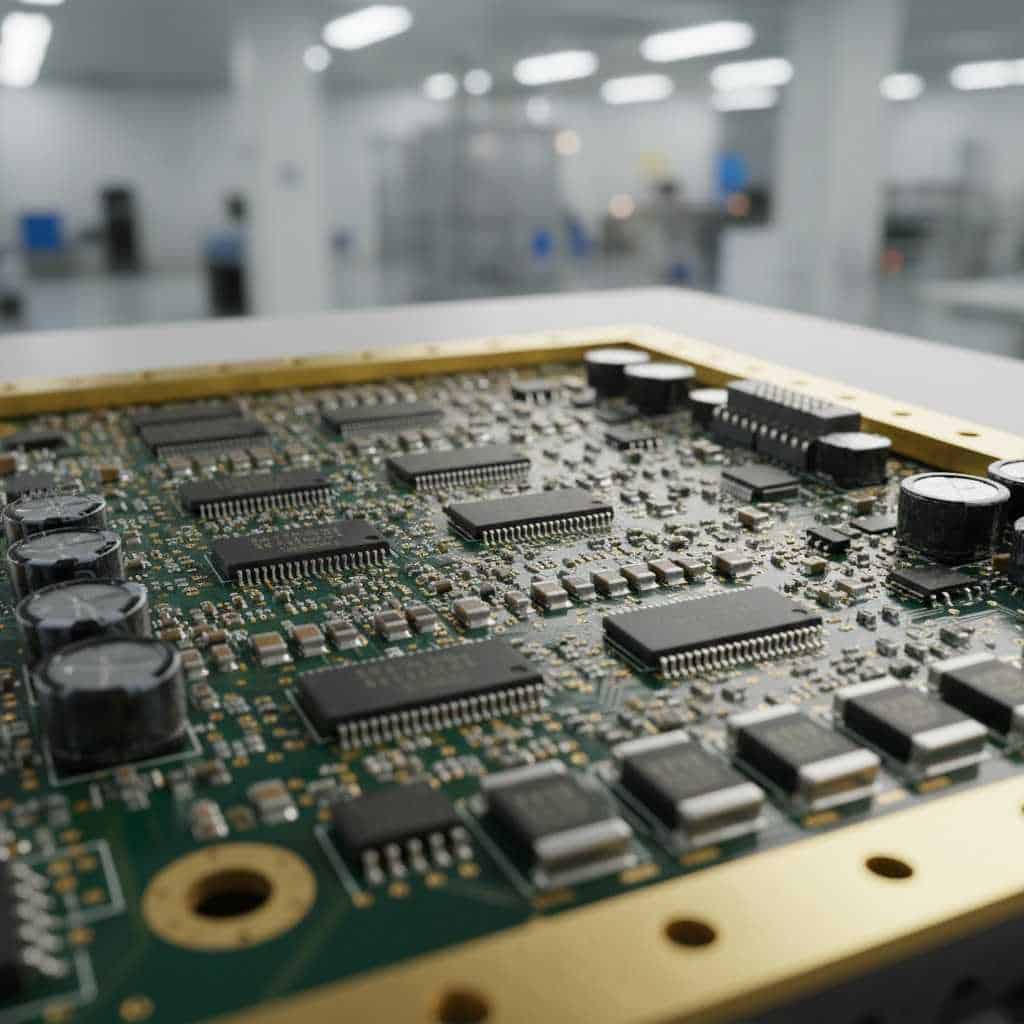
Military PCB assembly refers to the specialized manufacturing processes and stringent quality standards required to produce electronics that function reliably in extreme defense and aerospace environments.
Imagine you are developing a critical communication system for a defense contractor. After months of design, the prototype fails during a high-vibration simulation because a single solder joint cracked, or a dielectric layer delaminated under thermal stress. This failure isn’t just a technical setback; it’s a costly delay that could compromise mission safety and your reputation. The solution lies in strict adherence to Military PCB assembly protocols, which prioritize uncompromising durability and comprehensive testing over standard commercial speed.
In this guide, we will explore the essential standards and implementation strategies for high-reliability electronics.
Why are Mil-Spec standards vital for defense?
Military PCB assembly is essential because mission-critical electronics must withstand extreme temperatures, mechanical shocks, and prolonged vibrations without fail. These standards ensure that every component and solder joint meets the highest possible reliability threshold.
What defines the “Military” grade?
You will find that military grade is defined by zero tolerance for failure and extensive documentation. Unlike consumer electronics, these boards are built to last decades in the harshest conditions imaginable.
- Superior material selection for thermal stability.
- Stringent environmental testing (vibration, thermal shock).
- Traceability of every single component used in the build.
But wait, there’s more to it than just “toughness.”
Key Takeaway
Designing to military standards protects your hardware from environmental failure and ensures legal compliance in defense contracts.
| Feature | Commercial Standard | Military Standard |
| Lifecycle | 2-5 Years | 20+ Years |
| Environment | Controlled | Extreme / Rugged |
| Failure Tolerance | Low | Zero |
Strict adherence to these specs is the foundation of defense electronics.
How does IPC Class 3 differ from Class 2?
Military PCB assembly almost always requires IPC Class 3, which is the highest tier of the IPC standard, focusing on “High Performance/Harsh Environment Electronics.” While Class 2 is acceptable for general electronics, Class 3 demands much tighter tolerances for hole plating and solder fillets.
Is the extra inspection worth the cost?
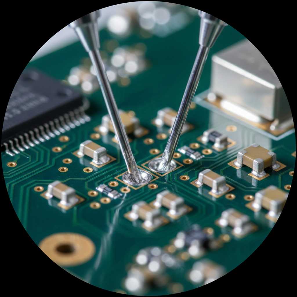
You need to consider that IPC Class 3 PCB Assembly involves significantly more rigorous visual and X-ray inspections. The goal is to ensure that even “hidden” defects like internal annular ring breakouts are non-existent.
- 180° minimum solder coverage on leads.
- Zero allowable “breaks” in the plated through-hole copper.
- Strict requirements for component alignment and cleanliness.
So, how do you decide between the two?
Key Takeaway
Use IPC Class 3 when uninterrupted service is mandatory and equipment downtime is not an option.
| Inspection Criteria | IPC Class 2 | IPC Class 3 |
| Barrel Fill | 75% Required | 75% – 100% Required |
| Annular Ring | Min 90° breakout allowed | No breakout allowed |
| Visual Inspection | Sampling | 100% Inspection |
Class 3 ensures that your SMT PCB Assembly remains intact under high stress.
To put IPC Class 3 into concrete numbers, here are the specific tolerances your design must meet:
- Copper plating thickness: Minimum 25 μm (0.001″) in all plated through-holes.
- Annular ring: Minimum 50 μm (0.002″) on external layers and 25 μm (0.001″) on internal layers — with zero breakout allowed.
- Conductor width reduction: No more than 20% reduction from the original artwork dimensions.
- Solder fill: 75% to 100% barrel fill required, depending on component type.
- Surface defects: Zero tolerance for measling, crazing, or delamination that affects board function.
These are not guidelines — they are pass/fail criteria. A board that meets Class 2 tolerances but falls short on even one Class 3 parameter will be rejected during inspection.
What are the core Military PCB assembly certifications?
Military PCB assembly is governed by specific performance specifications like MIL-PRF-31032 and MIL-PRF-55110. These certifications confirm that a facility has the equipment, training, and processes to handle complex defense projects.
Which certification is the most advanced?
MIL-PRF-31032 is currently considered the most comprehensive standard because it is based on a Quality Management System (QMS) specifically tailored for complex PCB technologies. You will find that it allows for more flexibility in design while maintaining extreme quality control.
- Verification of manufacturing process consistency.
- Frequent laboratory testing of production coupons.
- Authorized “Qualified Manufacturer List” (QML) status.
Believe it or not, this certification process can take years for a factory to achieve.
Key Takeaway
Selecting a certified partner ensures that your project meets the legal and technical requirements of the Department of Defense.
| Standard | Focus Area | Application |
| MIL-PRF-55110 | Rigid Boards | General Defense |
| MIL-PRF-31032 | Performance-Based | Advanced Defense/Aero |
| MIL-PRF-50884 | Flex/Rigid-Flex | Space/Aerospace |
Certifications act as a seal of trust for B2B defense procurement.
What about ITAR and NADCAP?
Beyond the MIL-PRF family, two additional compliance frameworks are critical for any defense PCB project.
ITAR (International Traffic in Arms Regulations) is administered by the U.S. Department of State and controls the export of defense-related technology. If your PCB design contains controlled technical data — which most defense electronics do — your assembly partner must be ITAR registered. This affects where the board can be manufactured, who can access the design files, and how data is stored and transmitted. Violations carry severe penalties, including fines up to $1 million per incident.
NADCAP (National Aerospace and Defense Contractors Accreditation Program) provides third-party audits of specific manufacturing processes. For military PCB assembly, the most relevant NADCAP accreditations cover:
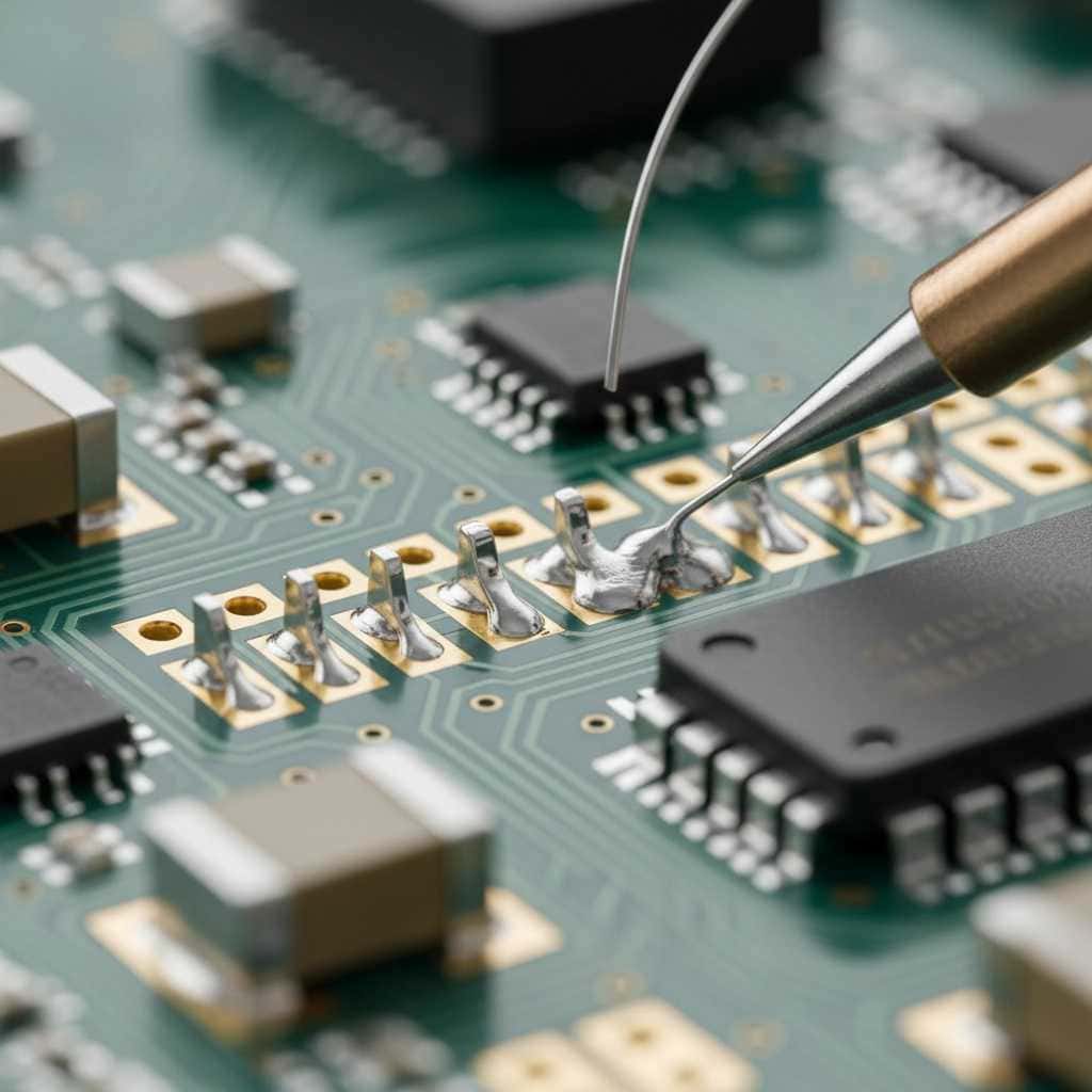
- Soldering (hand and automated)
- Conformal coating application
- Non-destructive testing (NDT)
- Chemical processing and plating
While NADCAP is not always mandatory, many Tier 1 defense primes — such as Lockheed Martin, Raytheon, and Northrop Grumman — require it from their supply chain. If you plan to work with these contractors, NADCAP accreditation is effectively a prerequisite.
Why is material selection critical in Military PCB assembly?
In Military PCB assembly, the choice of substrate material is a make-or-break decision. Materials must have a high Glass Transition Temperature ($T_g$) and low Coefficient of Thermal Expansion ($CTE$) to prevent delamination during rapid temperature changes.
Can standard FR4 handle military specs?
Generally, standard FR4 is insufficient; you will likely need High-$T_g$ FR4 or specialty materials like Polyimide or Rogers. These materials maintain their structural integrity even when exposed to the heat of continuous engine operation or high-speed flight.
- Resistance to “Outgassing” in vacuum environments.
- High Dielectric Constant stability.
- Enhanced moisture resistance for humid jungle or sea operations.
Are you prepared for the cost difference?
Key Takeaway
Investing in high-performance substrates upfront prevents catastrophic field failures caused by material fatigue.
| Material Property | Commercial FR4 | Polyimide (Military) |
| $T_g$ | $130-150^{\circ}C$ | $250^{\circ}C+$ |
| Moisture Absorption | Higher | Very Low |
| Thermal Stability | Moderate | Extreme |
High-end materials are the backbone of ruggedized electronics.
How does Through-Hole technology fit Military PCB assembly?
Even in the age of miniaturization, Through-Hole PCB Assembly remains a staple in military electronics. This is because through-hole components provide a mechanical bond that is far stronger than surface mount pads.
Why not just use SMT for everything?
You should know that components like heavy transformers and large connectors are prone to shearing off under vibration if they are only held by surface-level solder. Through-hole pins act like anchors, providing a robust physical connection that survives the rigors of combat.
- Superior mechanical bond strength for heavy parts.
- Better heat dissipation for high-power components.
- Ease of manual rework if field repairs are required.
The secret is often in the combination.
Key Takeaway
Combining SMT for logic and Through-Hole for power/connectors creates a Mixed Technology PCB Assembly that is both powerful and durable.
| Mounting Style | Mechanical Strength | Assembly Speed |
| Surface Mount (SMT) | Low – Moderate | Very High |
| Through-Hole (THT) | Very High | Moderate |
| Press-Fit | High | High |
THT remains the gold standard for mechanical durability in defense.
What testing is required for Military PCB assembly?

Military PCB assembly demands a “test-until-it-fails” mentality. Standard functional testing is just the beginning; the boards must also pass environmental stress screening (ESS) to ensure they aren’t the weak link in a larger system.
How do we simulate “Battlefield” conditions?
You will often see requirements for Thermal Cycling, where the board is moved between $-55^{\circ}C$ and $+125^{\circ}C$ within seconds. Additionally, vibration tables simulate the G-forces of a missile launch or a jet takeoff.
- X-ray inspection for internal solder voids.
- Ionic contamination testing to ensure long-term corrosion resistance.
- Flying probe and bed-of-nails functional testing.
Does this sound like overkill? Not when lives are on the line.
Key Takeaway
Rigorous testing identifies “infant mortality” failures in the factory, ensuring only 100% reliable boards reach the field.
| Test Type | Objective | Military Requirement |
| Thermal Shock | Check layer adhesion | Mandatory |
| Salt Spray | Corrosion resistance | For maritime use |
| X-Ray (AXI) | Solder integrity | Mandatory for Class 3 |
Testing is the only way to prove a design’s ruggedness.
How to manage documentation in Military PCB assembly?
In the world of Military PCB assembly, if it isn’t documented, it didn’t happen. Full traceability means you can track every resistor back to its original manufacturing batch and the date it was soldered.
Why is traceability so vital?
If a failure occurs in the field three years from now, the defense agency needs to know if it was a design flaw or a bad batch of components. You must provide a “Certificate of Conformance” (CoC) and detailed inspection reports with every delivery.
- Detailed Bill of Materials (BOM) with date codes.
- Photos of micro-sectioned coupons for copper plating verification.
- ESD and humidity control logs for the production floor.
You might find the paperwork takes as much time as the assembly itself!
Key Takeaway
Strong documentation practices protect you from liability and simplify the audit process for government contractors.
| Document Type | Purpose | Criticality |
| CoC | Proof of compliance | Vital |
| First Article Inspection | Validate process | Required |
| Material Certs | Verify source | Required |
Documentation is as important as the hardware itself in the defense sector.
What are the layout challenges for Military PCB assembly?
Designing a layout for Military PCB assembly requires more than just connecting the dots. You have to account for high-voltage arcing at high altitudes and manage heat in confined, fanless enclosures.
How do you prevent “Arcing” at high altitudes?
You will need to increase the spacing (creepage and clearance) between high-voltage traces because air becomes less resistive at high altitudes. Failure to do this can result in catastrophic short circuits when a plane reaches its cruising height.
- Wider traces to handle high-current surges.
- Thermal vias to pull heat into the chassis.
- Conformal coating to protect against moisture and dust.
The layout is where reliability is born.
Key Takeaway
Using a thorough DFM / DFA Engineering approach during the layout phase prevents costly redesigns after failing military certification.
| Layout Factor | Commercial Rule | Military Rule |
| Trace Spacing | Standard | High-Altitude Adjusted |
| Thermal Relief | Minimum | Enhanced for heat |
| Via Design | Standard | Tent or Fill for reliability |
Smart layout is the first step toward a compliant military product.
Is Military PCB assembly more expensive?
The short answer is yes, but you must view it as an investment in risk mitigation. The costs of Military PCB assembly are driven by high-end materials, extensive testing, and the skilled labor required for IPC Class 3 work.
Where does the extra money go?
You are paying for peace of mind. A large portion of the budget goes toward the 100% inspection rate and the specialized laboratory equipment needed to verify every mil-spec requirement.
- High-cost, long-lead-time mil-spec components.
- Specialized conformal coatings and potting compounds.
- Administrative costs for compliance and auditing.
But consider the alternative: what is the cost of a failed mission?
Key Takeaway
Partnering with a provider that offers Turnkey PCB Assembly can help consolidate these costs through better supply chain management.
| Cost Driver | Commercial | Military |
| Inspection | 5-10% | 30-40% |
| Materials | Standard | High-Performance |
| Testing | Functional | Environmental Stress |
Quality in military electronics is an investment, not an expense.
How to find a reliable Military PCB assembly partner?
Choosing the right partner for your Military PCB assembly project is the most important decision you will make. You need a factory that doesn’t just “say” they do military work but has the certifications and track record to prove it.
What questions should you ask a potential supplier?
You should ask about their experience with specific MIL-PRF standards and request to see their quality manuals. A visit to the facility to check their ESD controls and cleanroom environments is often mandatory for serious B2B defense projects.
- Do they have in-house X-ray and AOI capabilities?
- How do they manage component obsolescence (DMSMS)?
- What is their average yield for IPC Class 3 projects?
The right partner is more of a consultant than just a vendor.
Key Takeaway
A transparent partner who invites audits and shares detailed test data is your best asset in high-reliability manufacturing.
| Criteria | Good Partner | Great Partner |
| Certs | ISO 9001 | AS9100 / Mil-Spec |
| Tech | Standard SMT | Advanced THT & Mixed |
| Support | Sales-focused | Engineering-focused |
The right partner bridges the gap between design and defense-ready reality.
Military PCB Supplier Qualification Checklist
When evaluating a PCB assembly partner for defense projects, use this checklist to verify their actual capabilities — not just their marketing claims.
Certifications & Compliance
- IPC Class 3 / Class 3A (IPC-6012DS) certified production line
- ITAR registered with the U.S. Department of State
- AS9100D quality management system (or equivalent)
- ISO 9001:2015 as a baseline
- NADCAP accreditation for soldering, coating, or testing (if applicable)
Equipment & Process Capability
- In-house Automated X-ray Inspection (AXI) for BGA and hidden joint verification
- 3D Automated Optical Inspection (AOI) with Class 3 inspection programs
- Thermal profiling capability for both wave and reflow soldering
- Controlled-atmosphere or nitrogen reflow ovens
- ESD-protected and humidity-controlled production floor (documented logs)
Testing & Validation
- Thermal cycling capability: −55°C to +125°C
- Ionic contamination testing (per IPC-TM-650)
- Flying probe and/or bed-of-nails functional testing
- Microsection analysis for copper plating and barrel fill verification
- Salt spray testing capability for maritime-grade assemblies
Supply Chain & Documentation
- Component traceability to original manufacturer lot and date code
- DMSMS (Diminishing Manufacturing Sources) management program
- Certificate of Conformance (CoC) included with every shipment
- First Article Inspection Report (FAIR) per AS9102
Request this documentation before signing any contract. A qualified military PCB assembly partner will have these ready — if they hesitate, that tells you everything you need to know.
Real-World Application: Defense Communication System
To illustrate these standards in practice: our facility recently completed a 14-layer HDI board for a defense-grade tactical communication system. The project required IPC Class 3 inspection with full X-ray verification of over 800 BGA solder joints per board, Polyimide substrate with a Tg above 250°C, and ENIG surface finish for long-term storage reliability.
The boards passed the complete MIL-STD-810G environmental test suite, including 500 cycles of thermal shock between −55°C and +125°C, random vibration testing at 7.7 Grms across 20–2000 Hz, and salt fog exposure for 96 hours. The final yield rate was 99.2% at first-pass inspection — achieved through our DFM review process that identified and resolved three potential reliability risks before the first prototype was built.
This is what military-grade assembly looks like in practice: not just meeting the spec, but engineering the process to exceed it.
Conclusion
Navigating the complexities of Military PCB assembly and IPC Class 3 standards requires a deep commitment to quality and a meticulous eye for detail. From selecting the right high-$T_g$ materials to implementing rigorous thermal shock testing, every step must be optimized for maximum reliability. By adhering to these strict protocols, you ensure that your electronics can survive the most unforgiving environments on earth—and beyond.
We have addressed the critical pain points of failure-prone designs and costly compliance hurdles. Now, it is time to turn those challenges into a competitive advantage. At our facility, we pride ourselves on being a premier partner for high-reliability defense and aerospace projects. Contact us today to see how our engineering-first approach can bring your mission-critical designs to life. Our vision is to empower global security through uncompromising electronic excellence.
FAQ
Can I use commercial components in a Military PCB assembly?
No, generally you must use components specifically rated for military temperature ranges and reliability. These parts often have a different “M” prefix or specific military part numbers (MPNs) to ensure they meet defense specifications.
What is the best way to protect a military board from moisture?
The most effective method is applying a conformal coating, such as silicone, acrylic, or parylene. For the most extreme environments, “potting”—where the entire board is encased in a resin block—provides the ultimate protection against shock and humidity.
How do I know if my project requires MIL-PRF-31032?
You should check your contract’s “Flow-down” requirements. Usually, if the end application is for the Department of Defense (DoD) or a major aerospace prime contractor, they will specify exactly which MIL-PRF standard must be followed.
Can a Class 2 board be upgraded to Class 3 during assembly?
Rarely. IPC Class 3 requirements start at the design level (e.g., larger annular rings). If the layout doesn’t support Class 3 tolerances, simply inspecting it more strictly won’t make it compliant.
What is the lead time for mil-spec components?
It can be significantly longer than commercial parts, sometimes 20-40 weeks. It is crucial to work with a turnkey partner who can manage these long-lead items early in the design phase.
Upload your files today · Free DFM check before production · Ship worldwide
Get your PCB prototypes in as fast as 24 hours. We handle FR4, Rogers, and Flex up to 60 layers — free prototypes for 2–4 layer boards, no minimum order.
Just upload your Gerber + BOM — we source every part, assemble, and inspect (AOI + X‑Ray) so you don't have to chase suppliers. Boards ship in as fast as 24 hours.