
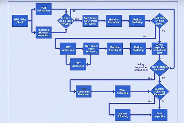
Quick answer: The PCBA manufacturing process converts approved design files, bare boards, and components into tested assemblies through 10 controlled steps: release review, build-package control, BOM validation, solder-paste and placement setup, soldering, inspection, programming and test, rework control, final evidence review, and buyer release.
For a buyer, the important question is not whether a supplier can show a generic flowchart. It is whether every step can be traced to the approved revision, BOM, component source, assembly drawing, test requirement, and release record.
Search results for this topic consistently favor a visible step-by-step process. The sequence below keeps that process easy to scan while showing the evidence a B2B buyer should check before approving production or shipment.
PCBA Manufacturing Process Flow: 10 Steps
- Approve files and acceptance criteria
- Release the controlled build package
- Validate the BOM and component sources
- Prepare stencil printing and placement
- Run placement, reflow, and through-hole soldering
- Inspect with visual, AOI, and X-ray methods
- Program and test the assembly
- Control rework and deviations
- Compile final release evidence
- Confirm the buyer release package
Step 1: Approve Files and Acceptance Criteria
The PCBA manufacturing process should prove that the assembly was built from the approved files, with approved components, under a controlled soldering and inspection route. A process that cannot show this evidence may still produce working samples, but it is weak for repeat orders and customer audits.
The buyer should separate three questions. Did the supplier understand the design package? Did the supplier build the same revision that purchasing approved? Did inspection and test confirm the risks that matter for this assembly? Each question needs a record.
Step 2: Release the Controlled Build Package
A reliable assembly order starts with files that agree with each other. The supplier needs Gerber or ODB++ data, fabrication drawing, BOM, approved vendor list if used, centroid or pick-and-place file, assembly drawing, polarity notes, special component instructions, and test expectations.
The highest-risk gap is mismatch between BOM, centroid, and assembly drawing. A package can be electrically correct but mechanically wrong for the land pattern. A polarity mark can be clear on a schematic but missing from the silkscreen or assembly drawing.
Use a release folder rather than scattered emails. For file-specific RFQ work, QueenEMS’ PCB assembly quote file checklist is the closer supporting page.
Step 3: Validate the BOM and Component Sources
BOM control shapes the PCBA manufacturing process before the first board reaches the printer. The supplier must know which manufacturer part numbers are approved, which alternates are allowed, which parts are customer-supplied, and which parts have date-code, package, or compliance limits.
A useful BOM has one row per fitted item. Each line should show reference designators, quantity per assembly, manufacturer, MPN, package, value, tolerance where relevant, lifecycle risk, and substitution rules. For DNP items, state the assembly decision directly.
Component control also affects schedule. A prototype may use cut tape from distribution, while production may need reels, trays, moisture-sensitive handling, or customer consignment. QueenEMS’ BOM for PCB assembly article goes deeper on those fields.
Step 4: Prepare Stencil Printing and Placement
Before SMT placement begins, the supplier checks the board, stencil, paste, feeder setup, program data, polarity, package orientation, and first-article plan. This stage is where many expensive mistakes are still cheap to catch.
The centroid file controls placement position and rotation, but it should not be trusted blindly. The supplier should compare it against the assembly drawing, silkscreen, package markings, and known library risks. BGAs, QFNs, connectors, LEDs, diodes, electrolytic capacitors, and asymmetric parts deserve special attention.
Stencil decisions also belong here. Aperture reduction, step stencil needs, fine-pitch paste release, thermal pad windowing, and paste type can affect solder joints before reflow starts.
Step 5: Run Placement, Reflow, and Through-Hole Soldering
Solder paste and reflow choices create risk when the assembly mixes fine-pitch SMT, large thermal pads, bottom-terminated components, sensitive parts, or mixed SMT/THT requirements. The process window must fit the component set, board finish, board thickness, and thermal mass.
A reflow profile is not just a temperature chart. It is a record that the board and components were soldered under a controlled thermal path. Parts with moisture sensitivity, high thermal mass, or special temperature limits should be identified before the profile is approved.
Through-hole work needs its own path. Selective soldering, wave soldering, hand insertion, press-fit, and manual soldering should be documented when they are part of the assembly. Mixed technology is not a problem by itself; undocumented process ownership is the problem.
Step 6: Inspect with Visual, AOI, and X-Ray Methods
AOI, X-ray, and visual inspection answer different questions. AOI checks visible placement and solder features. X-ray helps with hidden joints under BGAs, QFNs, LGAs, shields, or bottom-terminated parts. Manual visual inspection catches workmanship and handling issues that automated systems may not classify correctly.
A buyer should ask which inspection method is planned for the actual risk. A simple connector board may not need X-ray. A BGA-heavy assembly should not rely on visual inspection alone. A board with polarized parts needs orientation checks even if every solder joint looks clean.
Inspection evidence should be tied to lot and revision. If IPC class, customer criteria, or cosmetic limits apply, put them in the order package. For hidden solder-joint work, QueenEMS’ BGA assembly capability page is the more relevant service reference.
Step 7: Program and Test the Assembly
ICT, programming, and functional test matter when visual inspection cannot prove that the assembly works as intended. ICT can check nets, opens, shorts, values, and fixture-accessible functions. Programming loads firmware or configuration data. Functional test checks the assembly under a defined product behavior.
Not every prototype needs a production fixture. Early builds may use bench test instructions or customer-supplied test jigs. Production lots usually need a clearer test limit, fixture ownership, software version, pass/fail record, and rework disposition.
Test planning should begin during RFQ, not after assembly is complete. If the supplier needs pogo pins, boundary-scan access, programming adapters, power fixtures, or serialized labels, those items affect cost and schedule.
Step 8: Control Rework and Deviations
Rework and repair should be controlled by defined limits. A supplier may correct ordinary SMT defects within an accepted workmanship process, but design changes, component substitutions, lifted pads, repeated heating, or uncertain failures should trigger engineering review.
Purchasing may approve commercial schedule changes, but engineering should approve technical changes such as alternate parts, jumper wires, bodge fixes, component orientation changes, or fixture-driven modifications. Quality should define whether the result is acceptable for shipment.
Rework records are useful when prototypes move toward production. A hand fix that makes one sample work should become a design file, BOM, test, or process update before the next order. For formal design-change handling, connect this stage to QueenEMS’ engineering change notice process.
Step 9: Compile Final Release Evidence
The final release package should show what was built, what was inspected, what passed, and what exceptions remain. It does not need to be heavy for every order, but it should be clear enough for receiving, engineering, and purchasing to make the same decision.
Typical evidence includes final quantity, revision, BOM version, component exception list, inspection summary, test result, programming version, rework notes, packing list, photos when useful, and shipment tracking. For regulated or high-reliability products, add the required certificates, inspection reports, and traceability fields.
Step 10: Confirm the Buyer Release Package
Send QueenEMS the bare-board files, BOM, AVL, centroid, assembly drawing, panel preference, test instructions, firmware or programming needs, quality class, inspection expectations, and target build quantity. Mark any customer-supplied parts, DNP lines, approved alternates, and special packing needs.
The review should identify missing files, BOM risk, package/polarity concerns, process holds, test gaps, and evidence that should be priced before the purchase order. Use the QueenEMS contact page and include the assembly revision plus any known schedule constraint.
FAQ
What are the main PCBA manufacturing process steps?
The main steps are file review, BOM and component preparation, stencil and SMT setup, solder paste printing, pick and place, reflow, inspection, test, controlled rework, final inspection, packing, and shipment release.
Is AOI enough for PCBA quality control?
AOI is enough only for visible features that match the assembly risk. BGAs, QFNs, shields, and hidden joints may require X-ray or functional evidence as well.
What files are most often missing from a PCBA RFQ?
Centroid data, assembly drawings, polarity notes, AVL rules, DNP decisions, programming instructions, and test requirements are common gaps.
Can a supplier choose alternate components?
Only when the RFQ or PO allows it. Alternate parts should be named, reviewed, and recorded so purchasing savings do not become an uncontrolled engineering change.
Written by the QueenEMS Engineering Team
Upload your files today · Free DFM check before production · Ship worldwide
Get your PCB prototypes in as fast as 24 hours. We handle FR4, Rogers, and hybrid boards up to 40 layers in volume production, with advanced builds subject to engineering review — free prototypes for 2–4 layer FR-4 boards, no minimum order.
Just upload your Gerber + BOM — we source every part, assemble, and inspect (AOI + X‑Ray) so you don't have to chase suppliers. Boards ship in as fast as 24 hours.