
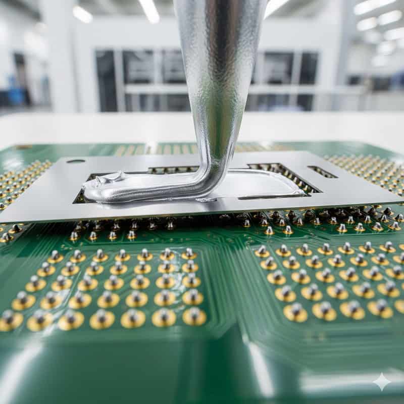
Soldering paste functions as a metallic adhesive binding components onto circuit boards. Hardware startups frequently experience catastrophic joint failures. Poor connections destroy valuable product runs causing massive financial losses. We deliver a tested strategy guaranteeing perfect bonds consistently. Choosing appropriate soldering paste completely eliminates these manufacturing headaches today.
1. What Exactly Is Soldering Paste Made Of?
Soldering paste primarily consists of tiny metal particles suspended within flux. Understanding soldering paste composition helps engineers prevent assembly defects effectively. Manufacturers mix tin alloys with chemical agents carefully. This precise mixture allows accurate component placement before heating occurs.
What Are The Primary Chemical Components?
Flux acts as a temporary adhesive holding parts securely. Here is the deal, flux also cleans oxidized surfaces during heating. Metal powder melts creating permanent electrical connections flawlessly.
- Metal alloy powder
- Rosin or synthetic resin
- Solvents and rheological additives
| Component | Function | Percentage |
| Metal Powder | Forms electrical joint | 90% by weight |
| Flux Medium | Removes surface oxidation | 10% by weight |
Analyzing these material ratios helps engineers improve printing performance during production.
Key Takeaway: Understanding paste formulation enables better material selection for high-reliability manufacturing processes.
2. How Does Soldering Paste Viscosity Affect Printing?

Viscosity determines how effectively paste flows through stencil apertures onto boards. Controlling soldering paste thickness prevents bridging between adjacent connection pads. High viscosity materials resist slumping after stencil release. Low viscosity variants flow easily filling microscopic stencil openings perfectly.
How Do You Manage Rheological Properties?
Temperature fluctuations heavily influence material flow characteristics on production floors. Listen to this, a minor temperature drop drastically thickens your material. Operators must maintain strict climate control continuously. Consistency guarantees repeatable deposits across thousands of printed circuit boards.
- Monitor ambient room temperature
- Control facility humidity levels
- Verify material storage conditions
| Viscosity Level | Application | Stencil Type |
| High | Fine pitch components | Laser cut |
| Medium | Standard SMT parts | Electroformed |
Reviewing viscosity parameters guarantees appropriate stencil matching for diverse product requirements.
Key Takeaway: Precise viscosity management remains absolutely necessary for achieving zero-defect printing results.
3. What Are Common Soldering Paste Flux Types?
Common flux varieties include rosin mildly activated and no-clean formulations. Selecting appropriate soldering paste flux dictates post-assembly cleaning requirements completely. Water-soluble options demand rigorous washing procedures afterward. No-clean types leave benign residues requiring zero subsequent washing steps.
Matching Flux With Specific Applications
Medical devices normally mandate complete residue removal avoiding contamination risks. You might be wondering, why do consumer electronics favor no-clean chemistries? Skipping the wash cycle significantly lowers overall manufacturing expenses. Fast-paced consumer markets demand peak production efficiency daily.
- Rosin Mildly Activated formulations
- Water-Soluble chemistries
- No-Clean flux types
| Flux Type | Post-Process Need | Industry Use |
| Water-Soluble | Intensive washing | High-reliability tech |
| No-Clean | Zero washing | Consumer electronics |
Matching your flux chemistry with specific product standards prevents premature failures.
Key Takeaway: Correct flux selection directly influences your final product lifespan and reliability.
4. How Do You Store Soldering Paste Properly?
Proper storage requires refrigeration keeping temperatures between two and ten degrees. Incorrect soldering paste storage rapidly degrades chemical flux activity. Heat exposure causes flux separation from metal powders quickly. Degraded material creates severe wetting issues during reflow heating operations.
What Are Cold Storage Protocols?
Operators must allow refrigerated materials sufficient time reaching room temperature naturally. Truth be told, forcing thermal acclimation destroys paste consistency immediately. Condensation forms if you open cold containers too quickly. Moisture trapped inside causes explosive solder balling during rapid heating.
- Maintain steady refrigeration temperatures
- Never freeze printing materials
- Record thermal exposure times
| Storage Condition | Shelf Life | Risk Factor |
| Refrigerated | Six months | Low risk |
| Room Temp | 24 hours | High risk |
Tracking material expiration dates drastically reduces unpredictable assembly line defects.
Key Takeaway: Strict temperature management preserves chemical integrity maximizing your production yield rates.
5. Why Does Soldering Paste Cause Tombstoning Defects?
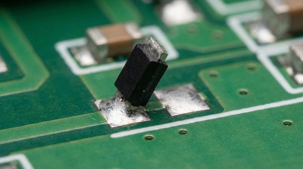
Tombstoning occurs when unequal surface tension forces pull small components upright. Using oxidized soldering paste creates uneven melting across component terminations. One pad melts faster pulling the resistor vertically upwards. Thermal imbalances during reflow profiles exacerbate this frustrating manufacturing issue.
How Do You Balance Thermal Dynamics?
Proper stencil design guarantees equal material deposits on both connection pads. Consider this situation, your heating zones ramp up too rapidly. Uneven heating melts one side prematurely triggering immediate component lift. Technicians must optimize oven temperature gradients carefully for every board.
- Verify equal pad dimensions
- Optimize thermal ramp rates
- Check material deposit volumes
| Defect Cause | Physical Result | Prevention Method |
| Uneven paste | Unequal pulling force | Stencil redesign |
| Rapid heating | Premature side melting | Profile tuning |
Adjusting thermal profiles along with precise printing completely eliminates tombstoning anomalies.
Key Takeaway: Symmetrical material deposition combined with balanced heating prevents vertical component lifting.
Tombstoning isn’t just a design flaw; it’s often the signature of a cheap assembly house rushing your boards through a generic, unoptimized reflow profile. At QueenEMS, our thermal engineers precisely calibrate oven gradients for every specific layout, guaranteeing symmetrical alloy melting. Stop paying for your manufacturer’s thermal imbalances. Let us assemble your next batch flawlessly.
6. How Can Soldering Paste Inspection Improve Yields?

Automated inspection systems utilize optical sensors measuring deposit volume precisely. Implementing advanced soldering paste inspection catches printing errors before component placement. Catching defects early saves massive rework costs later. Three-dimensional scanning verifies height across every single board pad accurately.
Utilizing SPI Technologies For Quality
Modern machinery generates detailed topological maps revealing microscopic printing flaws. Check this out, immediate feedback loops automatically correct stencil printer settings. Operators monitor real-time data preventing consecutive defective board runs. Statistical process control maintains tight manufacturing tolerances consistently all day.
- Measure precise deposit volume
- Verify accurate print alignment
- Detect missing material deposits
| Defect Type | Detection Method | System Action |
| Insufficient Volume | 3D Laser Scan | Trigger Alert |
| Material Smear | 2D Area Camera | Stop Printer |
Implementing real-time feedback loops guarantees superior surface mount assembly quality continuously.
Key Takeaway: Catching printing variations instantly prevents expensive scrapped assemblies down the line.
Relying on human eyes to inspect solder paste on fine-pitch components is a massive gamble. In industrial-grade manufacturing, hope is not a strategy. Our advanced 3D SPI (Solder Paste Inspection) systems measure the exact height and volume of every single pad before a single component is placed. We catch microscopic deviations instantly, ensuring true zero-defect production.
7. What Is The Ideal Soldering Paste Reflow Profile?
An ideal profile gradually raises temperatures activating flux before melting alloys. Programming accurate soldering paste profiles guarantees strong intermetallic bond formation. The preheat zone safely evaporates volatile solvents preventing dangerous splattering. Soak zones equalize temperatures across large and small components perfectly.
Managing Heating Zones Effectively
Reaching peak liquidus temperature quickly minimizes thermal damage risks significantly. Here is the catch, extending peak temperatures causes brittle joint formation. Cooling rates must remain controlled preventing thermal shock fractures completely. Expert technicians meticulously calibrate oven settings for every unique product run.
- Preheat zone solvent evaporation
- Thermal soak temperature equalization
- Reflow liquidus peak duration
| Heating Zone | Primary Purpose | Target Result |
| Preheat | Solvent evaporation | Prevent paste splatter |
| Reflow | Melt metal alloy | Form solid joint |
Customizing thermal zones for specific board designs guarantees robust mechanical connections.
Key Takeaway: Mastering reflow oven programming prevents weak solder joints from reaching customers.
8. How Do Environmental Factors Impact Soldering Paste?
High humidity environments accelerate moisture absorption degrading flux performance significantly. Exposing soldering paste towards humid air causes severe splatter during heating. Dry environments increase static electricity risks damaging sensitive electronic components. Facilities must maintain strictly controlled climatic conditions continuously without fail.
How Do You Control Facility Climates?
Optimal conditions typically require forty to fifty percent relative humidity levels. Believe it or not, a slight draft ruins stencil printing accuracy. Air currents dry out material sitting on top of stencils quickly. Enclosed printer cabinets protect materials from ambient factory drafts efficiently.
- Regulate ambient relative humidity
- Eliminate local air drafts
- Monitor factory temperature fluctuations
| Environmental Factor | Target Range | Risk If Ignored |
| Room Temperature | 22°C – 25°C | Viscosity degradation |
| Relative Humidity | 40% – 50% | Moisture absorption |
Enforcing strict environmental controls preserves material chemistry throughout demanding production shifts.
Key Takeaway: Investing in robust climate control infrastructure guarantees consistent daily manufacturing results.
9. Why Is Lead-Free Soldering Paste Mandated Globally?
International environmental regulations restrict hazardous substances protecting human health globally. Transitioning toward lead-free soldering paste complies with strict industry directives completely. Traditional tin-lead alloys cause severe ecological damage upon disposal. Modern alloys provide excellent reliability without toxic environmental impacts.
Adapting To New Manufacturing Standards
Lead-free alloys require significantly higher melting temperatures changing manufacturing dynamics entirely. This is where it gets interesting, elevated temperatures stress internal component structures. Engineers must select thermally resilient parts surviving harsher reflow conditions easily. Upgraded equipment manages these increased thermal requirements efficiently and safely.
- Compliance with global legislation
- Elimination of toxic heavy metals
- Implementation of higher temperature profiles
| Alloy Material | Melting Point | Environmental Impact |
| Tin-Lead | 183°C | Highly Toxic |
| Lead-Free SAC | 217°C | Eco-Friendly |
Upgrading your facility equipment handles these extreme thermal challenges effectively.
Key Takeaway: Adopting eco-friendly manufacturing materials guarantees global market access for your products.
10. How Does Soldering Paste Shape PCBA Miniaturization?
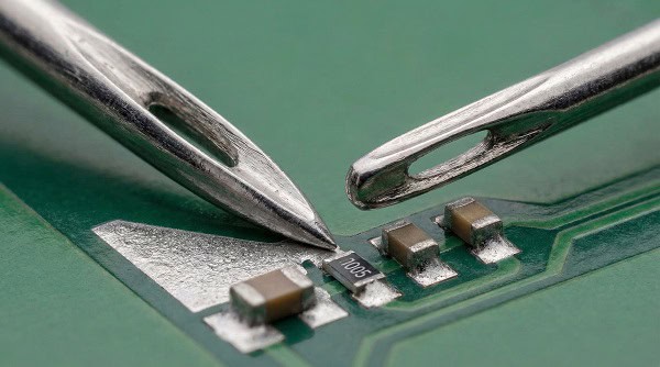
Type seven powder allows printing extremely tiny apertures for microchip placement. Utilizing ultra-fine soldering paste enables engineers packing more functionality into tighter spaces. Microscopic components demand flawless material deposition preventing electrical shorts. Smaller particle sizes flow smoothly through microscopic stencil holes easily.
Pushing Technological Boundaries Further
Wearable technology requires densely packed circuits demanding precision printing capabilities. The bottom line, miniaturization forces continuous innovation within material science fields. Finer powders oxidize faster requiring highly advanced chemical flux protection. Manufacturers constantly refine formulas meeting next-generation hardware demands effortlessly.
- Support for micro package sizes
- High-density interconnect board layouts
- Advanced micro-BGA escape routing
| Powder Type | Particle Size | Best Application |
| Type 3 | 25-45 microns | Standard SMT |
| Type 7 | 2-11 microns | Micro assemblies |
Selecting advanced fine-powder materials directly empowers your next breakthrough hardware design.
Key Takeaway: Leveraging microscopic printing technology keeps your electronic products incredibly competitive globally.
Pushing the boundaries of hardware miniaturization means you can no longer rely on low-end quick-turn shops. Micro-BGA and 01005 components demand Type 7 paste and absolute stencil precision. You design the future; let a true engineering-driven EMS partner build it. Experience the QueenEMS standard of reliability today—starting with a high-precision prototype.
Bringing It All Together
Selecting appropriate materials effectively prevents devastating manufacturing defects. Precision printing guarantees exceptionally durable electronic assemblies. Our dedicated factory team delivers expert guidance securing your mass production success. We transform ambitious hardware visions into reliable physical realities flawlessly. Please contact us today securing professional assembly solutions.
FAQ
Q1: Can I handle expired paste safely? You must discard expired materials immediately. Chemical degradation compromises flux activity resulting in guaranteed joint failures across your entire production batch.
Q2: What’s the best way reusing paste left on stencils? Never reuse scraped material for critical production runs. Ambient exposure alters viscosity causing unpredictable printing performance during subsequent manufacturing shifts.
Q3: How do I know if my material remains too cold? Check the container temperature using a calibrated infrared thermometer. Cold material feels physically chilled resisting smooth stirring motions during preparation.
Q4: What’s the best stencil thickness for standard SMT components? Five mils represents standard thickness for most traditional applications. This depth provides sufficient volume without causing excessive bridging between adjacent connection pads.
Q5: Can I mix different flux chemistries together? Absolutely avoid mixing different chemical formulations under any circumstances. Incompatible chemical reactions destroy material integrity causing massive soldering defects instantly.