
A Gerber file is a vector-based, 2D binary file format that serves as the universal “blueprint” for printed circuit board manufacturing, detailing every copper layer, solder mask, and drill hole required for production. Understanding what is a gerber file is essential for any engineer because it bridges the gap between digital design and physical reality. Imagine spending months perfecting a complex circuit layout, only to receive a batch of boards from the factory that are completely non-functional due to a tiny file conversion error. This is a common nightmare for B2B procurement managers—missing deadlines and blowing budgets because of simple data misalignments. But here’s the kicker… most of these issues are entirely preventable if you master the structure of your fabrication data. At QueenEMS, we act as your technical bridge, providing the expertise needed to turn your digital files into high-performance hardware with zero translation errors.
2. Why is understanding what is a gerber file critical for fabrication?
Understanding what is a gerber file is the first step in ensuring that your manufacturing partner accurately interprets your design intent without guesswork. These files contain the coordinate data and flash commands that tell the production machinery exactly where to deposit copper or apply solder mask.
How do Gerber files act as a universal language?
The Gerber format is the industry standard because it is independent of the CAD software you use, ensuring compatibility across all global factories.
- It provides a layer-by-layer breakdown of the board.
- It eliminates software-specific versioning issues.
- It serves as the final legal document for manufacturing specifications.
You might be wondering if your specific software’s native format is enough. While some factories accept CAD files, the Gerber remains the safest bet for reliable smt assembly results.
Key Takeaway
By providing standardized Gerber data, you minimize the risk of human error during the CAM (Computer-Aided Manufacturing) stage of production.
| File Component | Function in Fabrication |
| Layer Data | Defines copper traces and planes |
| Aperture List | Specifies sizes of pads and lines |
| Coordinate Data | Guides the laser or drill head |
This data ensures that every machine in the factory “speaks” the same language as your design software.
3. What is a gerber file format and which versions are standard?
When discussing what is a gerber file, you must distinguish between the various formats available, as using an outdated version can lead to significant delays. The industry has evolved from the ancient RS-274-D to the highly efficient Gerber X2 and X3 formats.
What are the differences between RS-274X and Gerber X2?
RS-274X is an “extended” format that includes aperture definitions within a single file, making it far more reliable than its predecessor.
- RS-274X: The most common format used in consumer electronics today.
- Gerber X2: Adds intelligence like layer stack-up info and netlist attributes.
- Gerber X3: The newest version, including component data for assembly.
Ready for the good part? Using X2 or X3 reduces the amount of manual communication required between you and the factory, as the files self-describe their purpose.
Key Takeaway
Choosing a modern format like RS-274X or X2 is the best way to prevent the “missing aperture” errors that plague older fabrication files.
| Format Version | Intelligence Level | Metadata Included |
| RS-274-D | Low | Requires separate aperture list |
| RS-274X | Medium | Built-in apertures |
| Gerber X2 | High | Layer attributes and stack-up |
Modern formats significantly reduce the back-and-forth emails during the pre-production engineering review.
4. How does the pcb fabrication process use what is a gerber file?
The pcb fabrication process uses what is a gerber file to generate the photolithography masks and drilling programs needed for each unique layer of your board. Once the factory receives your data, their CAM engineers load the Gerbers into a system to check for design rule violations.
What happens during the CAM review?
Before any copper is etched, your manufacturing partner verifies that your Gerber data is “producible” based on their specific factory tolerances.
- Tracing and spacing verification.
- Solder mask clearance checks.
- Drill-to-copper alignment audits.
Here’s the deal: if your files are messy or incomplete, this stage can take days instead of hours. This is why many hardware startups prefer to work with us, as we streamline the review process for faster time-to-market.
Key Takeaway
High-quality Gerber files act as the “source of truth” for the factory, ensuring that the physical board is an exact clone of your vision.
| CAM Task | Gerber Data Used | Result |
| Panelization | Board Outline Layer | Efficient material use |
| Etch Compensation | Copper Layers | Accurate trace widths |
| Mask Alignment | Solder Mask Layers | Prevented soldering shorts |
A rigorous CAM review is the secret to achieving high yields in complex manufacturing runs.
5. Why do you need a gerber file viewer before sending data?

You should always use a gerber file viewer to verify your exported data because what you see in your CAD software isn’t always what gets exported to the Gerber. Viewing the “raw” output allows you to catch missing pads, disconnected traces, or misaligned drill holes before the factory starts.
How do you spot errors in a Gerber viewer?
By loading all layers into a third-party viewer, you can see exactly how the factory’s machines will interpret your design.
- Verify that the board outline is on the correct layer.
- Check for “orphaned” copper or silver slivers.
- Ensure that silkscreen text isn’t overlapping solder pads.
Ready for the good part? This five-minute check can save you thousands of dollars in wasted materials and re-spinning costs. It is a critical step for robotics projects where precision is paramount.
Key Takeaway
The Gerber viewer is your last line of defense against “software translation” bugs that could ruin your entire production run.
| Common Error | Detection Method | Impact |
| Missing Drill Holes | Overlay Drill & Copper Layers | Open circuits |
| Mirrored Layers | Check Text Readability | Reversed components |
| Mask Encroachment | View Mask & Pad Layers | Solderability issues |
Using a viewer independent of your CAD tool provides the most objective verification of your manufacturing data.
6. What is a gerber file naming convention and why does it matter?
A consistent approach to what is a gerber file naming ensures that the factory knows exactly which file corresponds to which layer of the board. Without clear naming, a CAM engineer might accidentally swap the top and bottom layers, leading to a useless product.
How should you name your Gerber layers?
While most CAD tools have defaults, using descriptive names helps prevent confusion during the intake process at the pcb manufacturing files stage.
- Use suffixes like .GTL (Top Layer) and .GBL (Bottom Layer).
- Clearly label the .GKO (Keep-Out/Outline) file.
- Include a ReadMe file that lists the stack-up order.
What’s the real story? Clear communication at the file level shows the factory that you are a professional, which often results in smoother project handling.
Key Takeaway
Standardized naming conventions act as an extra layer of insurance against human error during the factory’s data import process.
| Layer Type | Suggested Extension | Alternative Suffix |
| Top Copper | .GTL | _Top_Copper |
| Solder Mask Top | .GTS | _Top_Mask |
| Drill File | .DRL | _Drill_Data |
Well-named files allow automated factory systems to sort and process your order with much higher speed.
7. How are drill files different from what is a gerber file?
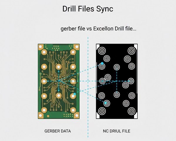
It is vital to realize that what is a gerber file usually covers the 2D copper and mask layers, while a separate NC Drill file (Excellon) is needed for the holes. Drill files contain the specific coordinates and tool sizes for every hole that needs to be bored through the laminate.
Why is the Drill file exported separately?
The machines that etch copper use different data logic than the CNC machines that drill holes, requiring a specific numeric control format.
- Apertures vs. Tools: Gerbers use D-codes; Drill files use T-codes.
- Plated vs. Non-Plated: Ensure your drill file distinguishes between the two.
- Coordinate Sync: The drill origin must match the Gerber origin exactly.
You might be wondering why some holes are missing from your board. Usually, it’s because the drill file wasn’t included in the final ZIP archive sent to the factory.
Key Takeaway
Never send a Gerber package without the corresponding Excellon Drill files; otherwise, your factory will have no way to create vias or mounting holes.
| File Type | Technology | Key Data |
| Gerber | Photolithography | Shapes and Traces |
| Excellon | CNC Drilling | Hole diameters and X/Y |
The synchronization between these two file types is what makes high-density telecom boards possible.
8. What is the role of what is a gerber file in multi-layer stack-ups?
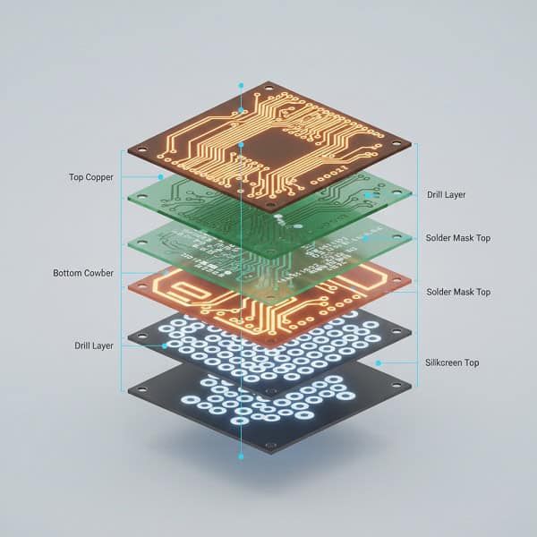
In complex tht pcb assembly projects, what is a gerber file becomes the roadmap for the entire multi-layer stack-up, including internal power and ground planes. Each layer requires its own individual Gerber file, and the sequence of these files is critical.
How do you communicate layer order to the factory?
Since Gerber files are essentially “flat” images, the factory relies on you to define the vertical sequence of the copper layers.
- Include a stack-up diagram or a CSV file.
- Number your files (e.g., L1_Top, L2_GND, L3_PWR, L4_Bot).
- Specify the dielectric thickness between each layer.
Here’s the deal: if you swap Layer 2 and Layer 3 in a high-speed design, the impedance of your traces will be ruined, causing the board to fail.
Key Takeaway
Providing a clear stack-up definition alongside your Gerber files is mandatory for any board with more than two layers.
| Layer | Type | Critical Info |
| Layer 1 | Signal | Controlled Impedance |
| Layer 2 | Ground | Reference Plane |
| Layer 3 | Power | Low DC Resistance |
Correct stack-up documentation ensures that your board meets the thermal and electrical needs of industry automation systems.
9. How to ensure what is a gerber file includes aperture definitions?
One of the most common reasons for fabrication failure is failing to include aperture definitions in the data, essentially telling the factory “where” to etch but not “how wide.” In modern extensions of what is a gerber file, these apertures are embedded directly.
What are apertures and D-codes?
Apertures define the shape and size of the “light” used to expose the photoresist; D-codes are the commands that call these shapes.
- D10: Example code for a circular pad.
- Flash: Creates a single point (like a pad).
- Draw: Creates a line (like a trace).
But here’s the kicker… if you use the old RS-274-D format, you must send a separate aperture list (.REP or .APT), or the factory will have no idea how thick your traces should be.
Key Takeaway
Always export in RS-274X or Gerber X2 to embed apertures automatically and eliminate the most common cause of fabrication holds.
| Code Type | Meaning | Action |
| D01 | Draw | Move with light on |
| D02 | Move | Move with light off |
| D03 | Flash | Pulse light once |
Understanding these codes helps you troubleshoot your output if the traces look incorrect in your viewer.
10. How to export what is a gerber file for high-reliability assembly?

When your goal is high-reliability bga assembly, what is a gerber file must include precise solder paste and silkscreen data to guide the pick-and-place machines. These “secondary” layers are just as important as the copper layers for a successful build.
What extra layers should be in your Gerber zip?
Beyond the copper, you must provide the layers that define how components are attached and labeled.
- Solder Paste Layer: Used to create the stencil for solder deposition.
- Silkscreen Layer: Provides reference designators for part placement.
- Assembly Drawing: A PDF or Gerber showing the final look of the populated board.
Ready for the good part? Providing clean solder paste Gerbers ensures that your BGAs and fine-pitch components are soldered without bridges or dry joints.
Key Takeaway
Including paste and assembly layers in your Gerber package is the difference between a “bare board” order and a successful pcb manufacturing files partnership.
| Extra Layer | Assembly Function | Impact |
| Paste Mask | Stencil Production | Solder joint quality |
| Silkscreen | Component ID | Easier troubleshooting |
| Solder Mask | Pad Definition | Prevents solder bridges |
Complete file sets allow us to move your project straight into production without delays.
Conclusion
What Is a Gerber File and How Is It Used in PCB Fabrication? has covered the entire lifecycle of manufacturing data, from format selection to final assembly prep. We’ve established that the Gerber file is the universal language of the electronics industry, ensuring that your design intent is perfectly captured by the factory’s machinery. The main finding is clear: precision in your Gerber output directly correlates to the reliability of your physical hardware. By following the best practices for file naming, viewer checks, and stack-up documentation, you can eliminate the costly errors that slow down your innovation. At QueenEMS, we are committed to being your long-term partner in this journey, offering the technical depth and manufacturing excellence you need to succeed. If you are ready to turn your designs into flawless hardware, contact us today. Our mission is to empower your vision with the most reliable manufacturing in the world.
FAQ
Q1: Can I send my CAD design files instead of Gerber files? Most professional factories prefer Gerber files because they are standardized and software-independent. While some manufacturers accept native CAD files, it increases the risk of versioning errors during the conversion process.
Q2: What is the best file format to use today? Gerber X2 is the current gold standard because it embeds metadata such as layer stack-up and netlist info directly into the files, reducing manual communication and the chance of errors.
Q3: How do I know if my Gerber files are correct? You should always load your exported ZIP file into a third-party Gerber viewer. This allows you to inspect the “raw” manufacturing data for any missing pads, traces, or alignment issues that might not be visible in your design software.
Q4: Why does the factory keep asking for a drill file? A standard Gerber file only describes 2D copper and mask layers. Drilling information is stored in a separate NC Drill (or Excellon) file which tells the CNC machine where to bore the holes.
Q5: How many files should be in a standard Gerber package? For a 2-layer board, you typically need at least 8 files: Top/Bottom Copper, Top/Bottom Solder Mask, Top/Bottom Silkscreen, Board Outline, and the NC Drill file. For multi-layer boards, this number increases accordingly.