
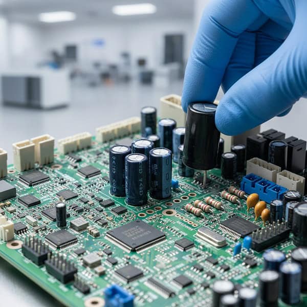
Through-Hole PCB Assembly represents the foundational method of mounting electronic components where leads are inserted into drilled holes on a circuit board and soldered to pads on the opposite side to ensure maximum mechanical bonding. While surface mount technology dominates high-density consumer gadgets, the sheer physical robustness provided by through-hole remains irreplaceable for industrial hardware, power supplies, and high-stress environments. You likely struggle with modern components vibrating loose or solder joints cracking under thermal expansion in your heavy-duty applications. Imagine the frustration of a critical field failure just because a surface-mounted connector couldn’t handle the physical leverage of a heavy cable. Here is the good news. Through-Hole PCB Assembly offers the mechanical “anchor” your mission-critical products need to survive years of rigorous use without failure.
1. What defines the core Through-Hole PCB Assembly process today?
The modern Through-Hole PCB Assembly process involves a precise sequence of drilling, component lead insertion, and specialized wave or selective soldering to create high-integrity electrical connections. In an era where miniaturization is king, this technique survives because it creates a physical bridge through the board that SMT simply cannot replicate.
- Precision drilling of copper-plated via holes.
- Manual or automated lead forming and insertion.
- Pre-heating the assembly to prevent thermal shock.
- Final soldering using wave or selective systems.
But here’s the kicker… not all through-hole work is manual anymore, as automated axial and radial insertion machines now provide high-speed precision for B2B production scales.
Is automated insertion faster than manual?
Automated insertion utilizes specialized machinery to place components like resistors and diodes at incredible speeds compared to human hands. While manual assembly is necessary for odd-form components, automation significantly reduces the lead time for high-volume industrial orders.
- Axial insertion for components with leads on both ends.
- Radial insertion for components with leads on one side.
- Enhanced consistency across thousands of units.
Key Takeaway: Using automation for THT components reduces human error and lowers the unit cost for large-scale industrial projects.
| Insertion Method | Speed | Flexibility | Best Use Case |
| Manual | Low | Very High | Prototype & Odd-form |
| Automated | High | Low | High-volume standardized |
The data suggests that a hybrid approach often yields the best balance of speed and reliability for complex boards.
2. Why does Through-Hole PCB Assembly remain the gold standard for durability?
Through-Hole PCB Assembly provides unparalleled mechanical strength because the component leads actually travel through the substrate rather than just sitting on the surface. When your product faces constant vibration or physical plugging and unplugging, this structural integrity becomes the difference between a long life and a quick RMA.
- Leads act as structural pillars within the board.
- Larger solder fillet surface area provides better grip.
- Resilience against mechanical shock during transport.
- Resistance to pulling forces on external connectors.
You might be wondering, “Isn’t SMT strong enough for most things?” For a smartphone, yes; but for a high-vibration aerospace sensor or a heavy-duty industrial controller, THT is the only way to sleep soundly at night.
How do THT joints handle thermal stress?
Because the solder joint encapsulates the lead within the barrel of the hole, it can expand and contract more uniformly than a surface-level bond. This prevents the “creeping” effect often seen in SMT pads when they are subjected to extreme temperature cycling in industrial environments.
- Superior dissipation of thermal energy.
- Reduced risk of pad lifting under heat.
- Uniform expansion across the X, Y, and Z axes.
Key Takeaway: Choosing THT for high-temperature environments ensures your solder joints won’t crack under repeated thermal cycling.
| Stress Type | THT Performance | SMT Performance | Advantage |
| Mechanical Pull | Excellent | Poor | THT |
| Vibration | High | Moderate | THT |
| Thermal Cycle | Very High | Moderate | THT |
Understanding these stress factors helps engineers choose the right mounting technology for harsh environment deployment.
3. How does Through-Hole PCB Assembly support high-power applications?
High-power Through-Hole PCB Assembly is the preferred choice for power converters and transformers because the leads can carry significantly higher current loads without overheating. When you are dealing with hundreds of volts or high-amperage draws, the physical mass of the THT lead and the surrounding solder joint helps manage the electrical load safely.
- Lower electrical resistance in the connection.
- Ability to use thicker leads for higher amperage.
- Enhanced heat sinking capabilities into the board.
- Higher safety margins for voltage spikes.
This is where it gets interesting… you can actually combine THT with heavy copper PCB technology to create a power distribution system that is virtually indestructible.
Can THT handle high-voltage isolation?
Yes, the physical distance provided by the lead spacing in through-hole designs allows for better creepage and clearance distances compared to tight SMT layouts. This is a critical safety requirement for medical devices and industrial power grids where arcing must be prevented at all costs.
- Easier to implement safety slots in the PCB.
- Better physical separation of high-voltage traces.
- Compliance with strict UL and IEC safety standards.
Key Takeaway: For power electronics, THT provides the physical clearances and current-carrying capacity necessary for safety and performance.
| Parameter | THT Rating | SMT Rating | Impact |
| Max Current | Up to 100A+ | Limited | Power Capacity |
| Voltage Gap | High | Low | Safety/Arcing |
High-power designs naturally gravitate toward through-hole to maintain stable operation under heavy electrical loads.
4. What are the primary soldering techniques in Through-Hole PCB Assembly?
In modern Through-Hole PCB Assembly, the two dominant soldering methods are wave soldering and selective soldering, each serving different design needs. While wave soldering is the classic choice for high-volume boards, selective soldering has become the hero for complex, high-density boards that mix THT and SMT components.
- Wave soldering for rapid, single-pass processing.
- Selective soldering for precise, localized joints.
- Hand soldering for highly sensitive or oversized parts.
- Nitrogen-shrouded environments to prevent oxidation.
Let’s be honest, choosing the wrong soldering method can lead to excessive rework or heat damage to your sensitive SMT components on the other side.
Why is selective soldering replacing wave in some cases?
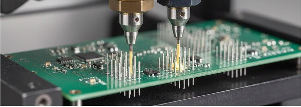
Selective soldering allows the manufacturer to program specific coordinates for the solder nozzle, protecting nearby SMT parts from the heat of a full solder wave. This flexibility is vital when you have a dense board where THT connectors are placed very close to delicate microprocessors.
- Eliminates the need for expensive solder masks.
- Reduced thermal stress on the entire PCB.
- Precise control over solder volume for every joint.
Key Takeaway: Selective soldering is the best solution for “Mixed Technology” boards where you need THT strength without risking SMT damage.
| Method | Precision | Speed | Cost (Setup) |
| Wave | Moderate | Very High | Lower |
| Selective | Very High | Moderate | Higher |
Selecting the right process depends on your component density and the total volume of the production run.
5. How do you prepare components for Through-Hole PCB Assembly?
Component preparation is a critical, yet often overlooked, stage of Through-Hole PCB Assembly that involves lead forming and cutting to ensure a perfect fit into the PCB. Properly formed leads prevent stress on the component body and ensure that the solder can flow evenly through the plated hole for a complete “barrel” fill.
- Lead bending to match hole spacing perfectly.
- Kinking leads to provide a “snap-in” fit during assembly.
- Cleaning leads to remove oxidation before soldering.
- Trimming leads to the correct length post-soldering.
Here’s the deal… if the leads are formed poorly, you risk micro-cracks in the component seals, which might not fail today but will certainly fail in the field.
What is the IPC standard for lead protrusion?
According to IPC-A-610 standards, leads should protrude slightly through the board to ensure a visible and inspectable solder fillet on the secondary side. This “protrusion” allows quality control teams to verify that the solder has climbed the lead correctly, ensuring a robust electrical connection.
- Minimum protrusion for electrical clearance.
- Maximum protrusion to prevent short circuits.
- Clear visibility for AOI (Automated Optical Inspection).
Key Takeaway: Proper lead preparation according to IPC standards ensures long-term reliability and easier quality inspection.
| Feature | Requirement | Reason |
| Lead Bend Radius | >2x Lead Dia | Prevent component damage |
| Protrusion | 0.5mm – 1.5mm | Inspection & Safety |
Strict adherence to preparation standards is what separates a professional B2B assembly from a hobbyist-level board.
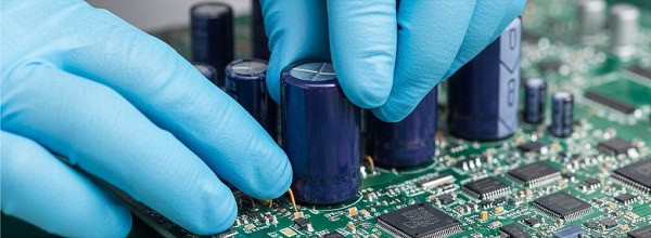
6. What role does manual labor play in Through-Hole PCB Assembly?
Despite the rise of robotics, skilled manual labor remains a cornerstone of Through-Hole PCB Assembly for complex, low-volume, or highly customized industrial products. Humans are far better than machines at handling “odd-form” components like large transformers, heavy-duty heat sinks, and specialized connectors that don’t come on standard reels.
- Expertise in handling delicate or heavy parts.
- Visual inspection during the assembly process.
- Ability to adapt to small-batch prototype changes.
- Installation of secondary hardware like brackets or fans.
Ready for the good part? Using a skilled workforce for THT allows for a “design for manufacturing” flexibility that fully automated lines simply cannot offer.
Can manual assembly be as consistent as machines?
While humans are naturally less consistent, a professional B2B factory uses “work instructions” and “assembly jigs” to ensure that every manual placement is identical. By using these guides, the factory maintains high quality while benefiting from the human ability to solve placement problems on the fly.
- Use of custom 3D-printed assembly jigs.
- Step-by-step visual workstation monitors.
- Rigorous in-process quality audits.
Key Takeaway: Manual assembly is essential for complex industrial designs where component variety exceeds machine capabilities.
| Aspect | Manual | Automated |
| Flexibility | High | Low |
| Setup Time | Minutes | Hours |
| Consistency | High (w/ Jigs) | Extreme |
A blend of human skill and mechanical aid provides the most reliable result for bespoke B2B hardware.
7. Is Through-Hole PCB Assembly compatible with SMT?
Most modern high-performance boards use a “Mixed Technology” approach where Through-Hole PCB Assembly is used for connectors and power stages, while SMT handles the logic and memory. This hybrid strategy allows engineers to maximize space with SMT while utilizing the mechanical advantages of THT where they are most needed.
- SMT for high-speed data and processing.
- THT for power inputs and external ports.
- Complex multi-stage soldering profiles.
- Optimal use of PCB real estate on both sides.
What’s the real story? You don’t have to choose one over the other; in fact, the best industrial designs nearly always use both to balance cost and strength.
How do you solder both on one board?
Typically, the SMT components are reflowed first, and then the THT components are added via selective soldering or manual methods afterward. This sequence prevents the heavy THT parts from falling off during the high-heat reflow oven stage or interfering with the solder paste printing.
- Initial SMT solder paste and reflow.
- Adhesive bonding for bottom-side SMT if needed.
- Secondary THT insertion and selective soldering.
Key Takeaway: Mixed technology is the industry standard for balancing high-speed performance with rugged physical durability.
| Technology | Best For | Mounting Style |
| SMT | Logic, Memory, RF | Surface Pads |
| THT | Power, Connectors | Through-Holes |
Combining these two allows you to create products that are both smart and incredibly tough.
8. What are the common challenges in Through-Hole PCB Assembly?
The biggest challenge in Through-Hole PCB Assembly is managing thermal mass, as large components and thick copper planes require significant heat to create a proper solder bond. If the heat isn’t managed correctly, you end up with “cold solder joints” where the solder hasn’t fully fused with the internal copper layers, leading to intermittent failures.
- Insufficient hole fill (wicking issues).
- Solder bridging between closely spaced pins.
- Shadowing effects during wave soldering.
- Component lifting due to thermal expansion.
Wait, there’s more… flux management is also critical, as any residue left inside the holes can lead to long-term corrosion or dendrite growth that shorts out your board.
How do you ensure 100% hole fill?
To achieve a perfect fill, the PCB must be pre-heated to the correct temperature, and the flux must be applied uniformly to break the surface tension of the molten solder. Professional assemblers use X-ray inspection to “see” inside the barrel and ensure the solder has climbed all the way to the top of the board.
- Optimized pre-heat ramp rates.
- High-quality active fluxes.
- X-ray and AOI verification.
Key Takeaway: Overcoming THT challenges requires advanced thermal profiling and high-end inspection equipment to guarantee internal joint integrity.
| Problem | Cause | Solution |
| Cold Joint | Low Heat | Thermal Profiling |
| Solder Bridge | Tight Pitch | Selective Soldering |
| Corrosion | Flux Residue | Aqueous Cleaning |
Proactive troubleshooting during the prototype phase prevents costly batch failures during mass production.
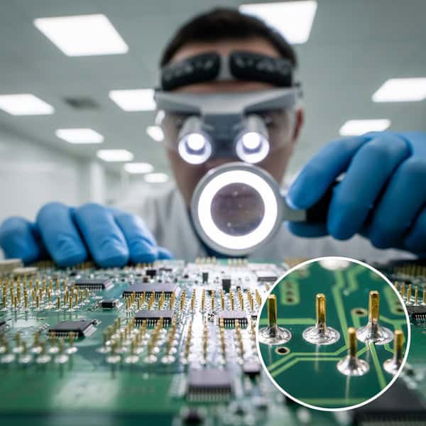
9. How do you inspect Through-Hole PCB Assembly for quality?
Quality control for Through-Hole PCB Assembly relies on a combination of visual inspection, AOI, and X-ray to ensure that every lead is perfectly encapsulated. Unlike SMT, where you only see the top surface, THT inspection must confirm that the solder has flowed through the entire thickness of the board to meet B2B reliability standards.
- Visual inspection for fillet shape and shine.
- AOI for component orientation and presence.
- X-ray for internal barrel fill and voiding.
- Functional testing to verify electrical paths.
The bottom line is… a pretty solder joint on the surface doesn’t mean the joint is strong; only internal inspection can prove the bond is complete.
Is X-ray mandatory for THT?
While not mandatory for every single board, X-ray is highly recommended for multi-layer PCBs (8+ layers) where the thermal mass makes it difficult to verify hole fill visually. For B2B clients in the medical or automotive sectors, X-ray reports are often a required part of the quality documentation package.
- Verification of hidden internal solder bonds.
- Detection of “voids” or air bubbles in the solder.
- Non-destructive testing for critical components.
Key Takeaway: Comprehensive inspection—including X-ray—is the only way to guarantee your product survives 10+ years in the field.
| Inspection Tool | What it Sees | Importance |
| Visual | Surface Fillet | Essential |
| AOI | Correct Part | High |
| X-Ray | Internal Fill | Critical (Multi-layer) |
Investing in high-level inspection during assembly saves thousands of dollars in potential field recalls later.
10. Where does Through-Hole PCB Assembly excel in the current market?
Through-Hole PCB Assembly continues to dominate in sectors like aerospace, military, and industrial power where failure is simply not an option. While SMT is for the “now,” THT is for the “forever,” providing the longevity and serviceability that B2B customers demand for their expensive infrastructure and mission-critical hardware.
- Aerospace and Defense (High vibration/G-force).
- Electric Vehicle (EV) Charging (High current).
- Industrial Automation (Longevity and repairability).
- High-End Audio (Signal integrity and massive components).
So, what’s the catch? THT takes up more space, so you must carefully balance your need for miniaturization against your need for a product that won’t break under pressure.
Is THT better for field repairs?
Absolutely. One of the biggest advantages for B2B equipment is that through-hole components can be desoldered and replaced in the field with basic tools. This makes it possible to repair a $10,000 industrial machine by replacing a $5 connector, rather than scrapping the entire board as is often the case with micro-SMT.
- Easy desoldering with manual pumps or wick.
- Larger pads are less likely to be damaged during repair.
- Lower barrier to entry for maintenance technicians.
Key Takeaway: Choosing THT for user-accessible parts like connectors can drastically reduce your long-term warranty and repair costs.
| Industry | Why THT? | Example Product |
| Automotive | Vibration Resistance | Engine Control Units |
| Power | Current Capacity | Solar Inverters |
| Medical | Reliability | Patient Monitors |
By focusing on these strengths, you can design products that stand out for their reliability in a world of disposable electronics.
Through-Hole PCB Assembly remains a vital pillar of the electronics industry, offering unmatched mechanical strength, high current handling, and extreme durability. We have discussed how the process works, why it survives alongside SMT, and how it provides a safety net for your most critical industrial applications. If you are tired of fragile boards and looking for a partner who understands the “heavy-duty” side of electronics, we are here to help. Contact us today to discuss how our professional engineering team can bring your most demanding PCB projects to life. Our commitment is to provide boards that don’t just work today, but continue to perform for decades.
FAQ
Q1: Can I mix SMT and through-hole components on the same side of a PCB?
Yes, this is very common in industrial designs. We usually reflow the SMT parts first and then use selective soldering to add the THT components without disturbing the existing chips.
Q2: What’s the best way to prevent solder bridging on high-density connectors?
Selective soldering is the most effective method because it uses a precise nozzle to apply solder only where it is needed. We also recommend using high-quality solder masks and proper lead lengths to minimize the risk.
Q3: How do I know if my design requires Through-Hole PCB Assembly instead of SMT?
If your product will experience high vibration, needs to handle more than 10 Amps, or features large connectors that users will pull on daily, you should definitely choose THT for those specific areas.
Q4: Can Through-Hole PCB Assembly be used on multi-layer boards?
Certainly, and it is a standard practice. However, it requires careful thermal management during soldering to ensure the heat reaches the internal layers for a 100% complete hole fill.
Q5: Is THT more expensive than SMT for mass production?
Generally, yes, because it involves more steps like lead forming and potentially manual placement. However, the cost is often offset by the reduction in field failures and the increased lifespan of the product.