
You design complex high-density circuit boards daily. Hidden manufacturing defects routinely ruin product launches without proper verification. These invisible errors cause catastrophic failures quickly. Frustrated clients will drain your engineering budget entirely. Fortunately, implementing a highly precise flying probe test immediately catches microscopic faults before shipping occurs. Finding faults early saves massive capital continuously. Protecting your reputation requires stringent quality protocols constantly. Testing validates every single physical connection flawlessly. Modern factories rely heavily on automated inspection technologies. You must demand rigorous verification from manufacturing partners. Quality dictates long-term commercial success consistently.
Contents
- 1. What exactly is a flying probe test?
- 2. How does a flying probe test compare to ICT?
- 3. What components make up a flying probe test system?
- 4. What parameters does a flying probe test measure?
- 5. What are the main flying probe test advantages?
- 6. What are the limitations of a flying probe test?
- 7. How do you optimize a flying probe test design?
- 8. How do you fix flying probe test failures?
- 9. When is a flying probe test the best strategy?
- 10. What files do you need for a flying probe test?
1. What exactly is a flying probe test?
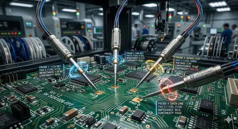
A flying probe test represents an automated electrical inspection method utilizing highly precise moving needles. Engineers program these robotic arms contacting specific copper pads quickly. This system validates continuity across complex electronic assemblies efficiently. Factories deploy this machinery during early production stages regularly. Skipping this verification risks catastrophic field failures constantly. Quality control departments depend heavily upon accurate diagnostic feedback. You receive detailed reports highlighting short circuits immediately. Manufacturing partners utilize advanced robotics guaranteeing product reliability. Diagnostic accuracy defines modern electronic production success deeply.
How does the basic mechanism operate?
These robotic needles travel rapidly across your printed circuit board. Here is the deal: Multiple arms move independently across both sides simultaneously. They measure resistance values between tiny copper vias accurately. Precision motors drive every single test probe flawlessly. Optical cameras align physical setups perfectly. Systems require zero custom mechanical fixtures beforehand. Programming happens directly from your provided CAD data smoothly. Setup times remain incredibly short compared against traditional methods. Hardware verification completes quickly.
- Robotic arms target specific component pads accurately.
- Cameras provide precise optical alignment data continuously.
- Software controls every individual probe movement completely.
Why do engineers rely on this method?
Engineers trust moving needles because setup requires minimal capital investment. Truth be told: Custom fixtures cost thousands of dollars unnecessarily. This robotic technique verifies complicated trace routing flawlessly. Diagnosing faults becomes incredibly straightforward during prototyping phases. You avoid paying massive upfront tooling fees entirely. Modifying test parameters takes only several minutes usually. Design changes process seamlessly through updated software commands. Hardware iterations happen rapidly safely.
| Feature Parameter | Moving Probe System | Traditional Bed of Nails |
|---|---|---|
| Setup Time | Several hours | Multiple weeks |
| Fixture Cost | Zero dollars | Extremely expensive |
| Design Flexibility | Exceptionally high | Terribly low |
This comparative matrix proves how fixtureless robotics eliminate massive financial barriers during initial hardware development.
Key Takeaway: You save immense capital while maintaining extreme diagnostic flexibility adopting fixtureless robotic inspection techniques early.
2. How does a flying probe test compare to ICT?
A flying probe test compares favorably by eliminating expensive custom fixtures while operating at noticeably slower inspection speeds. Production managers constantly debate between these two distinct verification strategies. Your unique manufacturing volume dictates which technology works best. In-circuit testing requires massive custom mechanical bed-of-nails assemblies. Those dedicated fixtures hit every single node simultaneously. Robotic needles touch only a few points concurrently. Volume production demands instantaneous multi-node verification typically. Low-volume runs cannot justify massive upfront tooling expenses. Strategic planning maximizes your operational budget perfectly.
Where do these testing methods differ most?
The primary distinction lies entirely within mechanical tooling requirements. Picture this: A custom bed-of-nails fixture takes weeks fabricating. Fixtureless systems start evaluating boards almost immediately after programming. In-circuit diagnostics check an entire assembly within seconds. Robotic arms need several minutes finishing one board. You must balance required throughput against available tooling budgets. Hardware revisions render expensive ICT fixtures completely useless instantly. Moving needles adapt instantly via simple software updates. Production scaling requires careful technological transitions.
- ICT evaluates entire boards almost instantaneously.
- Robotic needles provide ultimate design iteration flexibility.
- Bed-of-nails fixtures demand massive upfront capital.
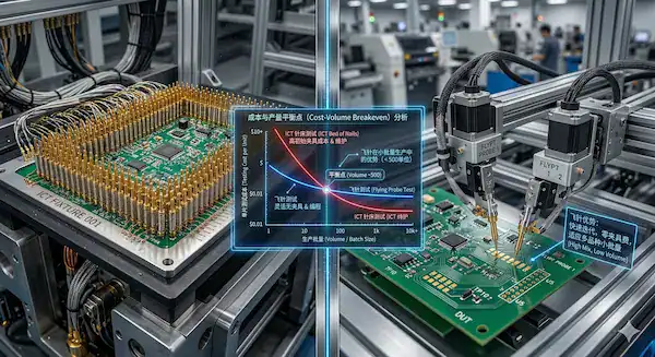
At what volume does switching make financial sense?
Many designers ask when upgrading becomes financially mandatory. Now let us get down to business: ICT fixtures run between $3,000 through $20,000 typically. Moving probe machines cost roughly $1 through $5 per board. Calculating your breakeven point prevents wasting limited startup capital. Volume levels hitting 500 units usually favor robotic techniques. Approaching 1,000 units pushes financial math toward dedicated fixtures. You must analyze projected sales before committing funds blindly. Commercial success demands ruthless financial optimization.
| Metric Evaluated | Fixtureless Robotics | In-Circuit Testing (ICT) | Functional Testing (FCT) |
|---|---|---|---|
| Upfront Tooling | Zero capital | Massive investment | High investment |
| Evaluation Speed | Relatively slow | Extremely fast | Moderately fast |
| BGA Access | Severely restricted | Very good | Excellent |
| Volume Target | Prototypes | Mass manufacturing | Final validation |
This financial breakdown reveals exactly when scaling production necessitates transitioning toward dedicated mechanical inspection setups.
Key Takeaway: You should fiercely utilize fixtureless robotics below 1,000 units before transitioning toward massive dedicated tooling setups.
3. What components make up a flying probe test system?
A flying probe test system relies heavily upon independent moving probes alongside advanced control software. These primary elements work together harmoniously detecting microscopic faults. High-precision stepper motors drive titanium needles across your board. Internal staging platforms secure bare printed circuits firmly. Advanced algorithms calculate optimal travel paths dynamically. Industrial cameras verify physical pad alignments perfectly. Factory technicians monitor diagnostic readouts through intuitive graphical interfaces. Everything functions cohesively without requiring hardwired customized connections. Modern machinery integrates deeply with advanced digital frameworks.
How do the moving needles operate?
Robotic arms execute highly choreographed movements flawlessly. You might be wondering: Precision mechanics position fine tips within tight micrometer tolerances. Four independent arms access top surfaces simultaneously. Specialized sensors detect microscopic height variations dynamically. They apply specific downward pressure avoiding delicate trace damage. Needles deliver electrical signals reading returned voltage values accurately. Contact angles remain slightly skewed preventing heavy solder marks. Mechanical precision dictates diagnostic accuracy absolutely.
- Needles slide diagonally preventing deep gouges.
- Z-axis sensors monitor downward pressure constantly.
- Multiple arms cross without colliding ever.
What role does the control software play?
Computer algorithms orchestrate every single robotic movement completely. Here is the kicker: Intelligent pathfinding reduces total inspection time drastically. Software translates your original CAD data into physical coordinates. The central processor flags anomalous resistance readings instantly. Engineers adjust tolerance thresholds through digital menus easily. Data logs capture specific failure points facilitating rapid repairs. Visual defect maps display exactly where shorts exist. Software drives modern manufacturing intelligence continually.
| Core Component | Primary Function | Operational Benefit |
|---|---|---|
| Titanium Needles | Making electrical contact | Zero custom tooling |
| Control Algorithms | Routing travel paths | Faster inspection cycles |
| Optical Cameras | Aligning physical boards | Precise pad targeting |
This architectural summary explains why modern diagnostic machines achieve unparalleled precision alongside total operational flexibility.
Key Takeaway: You gain extraordinary diagnostic accuracy because intelligent software dynamically controls every microscopic needle movement flawlessly.
4. What parameters does a flying probe test measure?
A flying probe test accurately measures electrical resistance alongside micro-shorts across circuits. Diagnostic machines force electrical currents through specific copper traces. Internal sensors record voltage drops pinpointing open connections immediately. Many developers ask if robotics verify incorrect component values. Modern equipment identifies wrong resistors reliably. Checking diode orientations prevents catastrophic power failures later. Analog signatures reveal completely missing microscopic parts effortlessly. You receive comprehensive electrical validation covering basic passive elements thoroughly. Diagnostic depth guarantees basic hardware integrity fully.
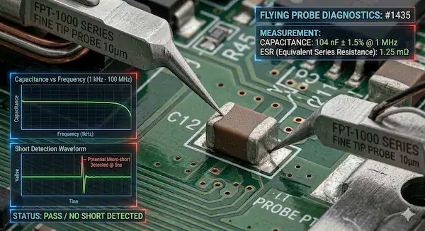
Can it detect incorrect component values?
Robotic needles verify analog passive devices exceptionally well. Truth be told: Applying low voltages determines exact resistor specifications accurately. Measuring discharge rates validates tiny ceramic capacitors perfectly. Inductors present specific phase shifts revealing true henries clearly. However verifying complex digital logic functions remains impossible. Checking microprocessors requires fully powered functional diagnostics. Fixtureless machines excel identifying bad passive placements strictly. You must understand diagnostic limitations thoroughly.
- Resistance checks catch incorrect pull-up values.
- Capacitance tests identify completely missing decoupling caps.
- Polarity verifications prevent dangerous reversed diodes.
How does it identify microscopic shorts?
Detecting microscopic solder bridges prevents smoking power supplies later. Let us face facts: Applying high-voltage pulses exposes hidden micro-shorts easily. Advanced impedance measurements find unexpected parallel connections quickly. The machine compares measured values against known good models. Anomalous current flows trigger immediate failure warnings loud. Technicians receive specific coordinate locations guiding manual rework efforts. Identifying tiny manufacturing flaws protects your reputation completely. Defect capture rates determine final product quality deeply.
| Parameter Measured | Defect Caught | Diagnostic Limitation |
|---|---|---|
| Electrical Resistance | Wrong resistor values | Cannot test active ICs |
| Capacitance Curves | Missing ceramic capacitors | Struggles checking parallel caps |
| Circuit Continuity | Broken copper traces | Misses high-speed signal issues |
This diagnostic capability matrix demonstrates exactly which specific hardware faults fixtureless robotics reliably identify during manufacturing.
Key Takeaway: You must leverage fixtureless diagnostics catching incorrect passive values while realizing fully powered functional validation remains necessary elsewhere.
5. What are the main flying probe test advantages?
The main flying probe test advantages include zero fixture costs alongside extreme flexibility during design iterations. Startups love this technology avoiding massive upfront financial burdens. You launch new hardware designs without waiting weeks. Programming takes hours rather than building physical nail beds. Revisions process effortlessly following simple digital file updates. Your time toward market shrinks dramatically using robotic diagnostics. Manufacturing partners pivot between different client layouts instantly. Production floors maximize efficiency handling diverse low-volume portfolios effectively. Agility defines successful modern hardware startups always.
Why is flexibility crucial for prototyping?
Prototypes undergo constant engineering revisions practically overnight. This is where things get interesting: Moving pads slightly ruins expensive hardwired fixtures permanently. Fixtureless robotics require only an updated CAD file upload. You modify trace routing freely without incurring mechanical penalties. Engineers test multiple design variants simultaneously evaluating optimal performance. Hardware development cycles accelerate exponentially through digital adaptability. Your team innovates fearlessly knowing diagnostic processes remain agile. Flexibility eliminates agonizing engineering bottlenecks completely.
- Digital updates replace expensive mechanical modifications perfectly.
- Testing multiple iterations requires zero extra capital.
- Factory setup times drop from weeks into hours.
How does it eliminate upfront tooling expenses?
Eliminating custom tooling frees massive capital funding marketing efforts. Ready for the good part? Traditional nails require custom drilled acrylic plates heavily. Fabricating those blocks demands specialized machining equipment continuously. You completely bypass those expensive mechanical manufacturing steps. Robotic platforms utilize universal holding mechanisms securing any board. Factories pass these incredible financial savings directly toward clients. Your budget stretches further supporting additional hardware features. Preserving cash extends runway significantly.
| Production Advantage | Financial Impact | Scheduling Impact |
|---|---|---|
| Zero Custom Tooling | Saves thousands completely | Eliminates weeks waiting |
| Digital Reprogramming | Zero revision costs | Minutes replacing days |
| Universal Clamping | Reduces NRE charges | Instant job swapping |
This advantage breakdown highlights exactly how agile digital diagnostics accelerate hardware development while preserving limited startup capital.
Key Takeaway: You significantly accelerate hardware launches because digital adaptability completely eliminates agonizing delays associated with fabricating custom mechanical tooling.
6. What are the limitations of a flying probe test?
The primary limitations of a flying probe test involve slow processing speeds alongside restricted physical access underneath bulky components. You cannot physically touch solder joints hidden beneath silicon. Ball grid arrays present massive accessibility challenges constantly. Testing an entire dense layout takes several minutes. High-volume manufacturing lines cannot tolerate such agonizing bottlenecks. Complex digital logic remains completely unverified without power. Engineers must deploy complementary inspection technologies filling these gaps. Relying solely upon moving needles leaves dangerous blind spots. Comprehensive quality strategies blend multiple technologies seamlessly.
How do you test hidden BGA connections?
Many developers ask how robotics verify invisible bottom pads. What is the real story? Needles cannot penetrate solid silicon chips physically. You must route fan-out vias placing tiny test points outside. Advanced TestJet technologies measure internal lead frame capacitance remotely. This validates correct chip placement without requiring direct physical contact. X-ray inspection remains absolutely mandatory catching hidden solder voids. Combining robotics with radiography guarantees flawless complex component attachments. Hybrid validation strategies ensure total product reliability.
- Fan-out vias provide accessible exterior probing targets.
- TestJet capacitance verifies internal silicon wire bonds.
- X-ray imaging catches hidden microscopic solder bridges.
Why is testing speed significantly reduced?
Robotic arms travel sequentially across every single electrical node. Consider this reality: Hitting thousands of pads takes considerable mechanical time. In-circuit nail beds press every node concurrently within seconds. Complex server boards might require twenty minutes using robotics. Production managers must calculate throughput requirements very carefully. Mass manufacturing absolutely demands dedicated instantaneous validation fixtures. Moving needles serve specialized low-volume production requirements exclusively. Speed dictates manufacturing strategy entirely.
| Technology Limitation | Root Cause | Engineering Workaround |
|---|---|---|
| Slow Evaluation Speed | Sequential arm movement | Upgrade toward ICT fixtures |
| Hidden BGA Joints | Physical silicon blockage | Implement TestJet and X-ray |
| No Active Logic | Unpowered circuit state | Perform powered functional validation |
This limitation chart clarifies exactly where moving needles fail while providing actionable engineering workarounds circumventing those obstacles.
Key Takeaway: You must proactively integrate advanced radiography alongside strategic fan-out vias catching defects hidden beneath complicated silicon packages.
7. How do you optimize a flying probe test design?
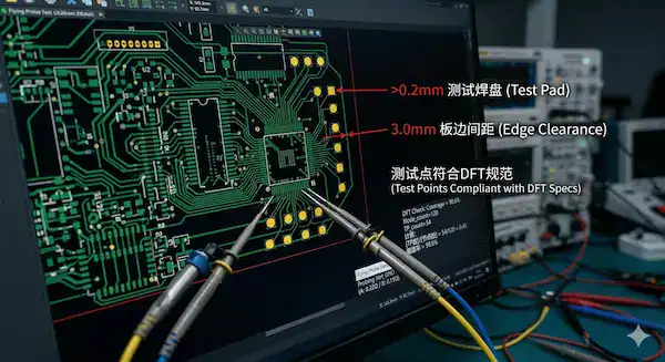
You optimize a flying probe test design strategically placing accessible test points alongside strictly following DFT guidelines. Design for testability dictates your ultimate manufacturing success deeply. Creating layouts lacking exposed pads causes agonizing production delays. Needles require specific physical target areas preventing mechanical slippage. You must maintain adequate spacing separating adjacent copper elements. Following strict geometric rules protects delicate components from damage. Factories provide comprehensive rulebooks guiding your CAD layout process. Planning diagnostics early prevents expensive post-design modifications entirely. Proactive engineering prevents reactive manufacturing nightmares.
What are the primary test point rules?
Engineers must provide adequately sized targets guaranteeing reliable needle contact. Let us face facts: Pads smaller than 0.2mm cause frustrating false opens. Maintaining safe clearances prevents probes crashing into tall capacitors. Keep probing targets away from fragile board edges strictly. Do not place test vias directly underneath bulky overhangs. Your design team must prioritize diagnostic accessibility fiercely. Staggering tiny targets helps bulky robotic arms maneuver cleanly. Good geometry guarantees flawless mechanical interaction continually.
- Minimum pad diameter should exceed 0.2mm ideally.
- Keep targets 3mm away from physical board edges.
- Maintain 0.5mm clearance around tall component bodies.
How do you implement a robust DFT checklist?
Deploying formal checklists prevents amateur layout mistakes completely. Here is the kicker: Reviewing accessibility before exporting Gerbers saves massive headaches. Verify every single net contains at least one target. Ensure bottom-side pads lack heavy solder mask coverings. Check that BGA fan-outs leave enough room for needles. Share your proposed layout with manufacturing partners early. Their software simulates robotic movements catching impossible angles. Collaborative engineering yields superior manufacturing outcomes constantly.
| DFT Design Rule | Geometric Parameter | Manufacturing Benefit |
|---|---|---|
| Target Pad Size | > 0.2mm diameter | Prevents false open failures |
| Edge Clearance | > 3.0mm distance | Avoids mechanical clamping damage |
| Component Spacing | > 0.5mm away | Stops needles hitting capacitors |
This design rule table provides exact geometric parameters guaranteeing your circuit layout accommodates robotic inspection mechanics flawlessly.
Key Takeaway: You absolutely must implement strict geometric clearances during initial CAD layout phases guaranteeing flawless robotic diagnostic accessibility.
8. How do you fix flying probe test failures?
You fix flying probe test failures recalibrating probe pressure alongside adjusting software thresholds accurately. False readings cause immense frustration during final quality assurance. Needles slipping off tiny pads register completely fake open circuits. Microscopic debris blocks electrical continuity triggering unnecessary rework tickets. Technicians must differentiate between machine errors versus true hardware faults. Adjusting mechanical parameters resolves most confusing diagnostic discrepancies. Properly maintaining copper surfaces ensures pristine electrical signal transmission. You must understand common failure modes identifying root causes quickly. Diagnostic troubleshooting remains highly specialized engineering work.
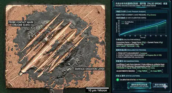
What causes frustrating false open readings?
False opens happen when robotic needles fail making solid contact. Truth be told: Dull tips cannot pierce tough surface oxidation layers. Incorrect board leveling leaves needles hanging above lower pads. Tall neighboring components physically block arms reaching intended targets. You fix this applying slightly more downward pressure. Regularly replacing worn titanium tips remains absolutely mandatory. Keeping bare boards clean prevents microscopic insulating dirt layers. Cleanliness prevents bizarre diagnostic anomalies completely.
- Worn tips fail piercing surface oxidation completely.
- Tall components block arms causing physical interference.
- Warped boards misalign specific Z-axis height calculations.
How can you prevent probe mark damage?
Aggressive downward pressure leaves permanent dents damaging soft copper traces. Now let us get down to business: Needles must strike pads using precise skewed angles. Hitting dead center drives sharp metal straight through traces. Software dictates angled approaches dragging tips slightly across surfaces. This grazing technique breaks oxidation without causing structural harm. Engineers balance electrical contact against physical material preservation carefully. Properly calibrated machines leave barely visible microscopic surface scratches. Machine calibration preserves physical board integrity perfectly.
| Failure Symptom | Probable Root Cause | Corrective Action |
|---|---|---|
| Persistent False Opens | Severe pad oxidation | Increase needle wiping pressure |
| False Short Circuits | Contaminated machine tips | Clean titanium probes thoroughly |
| Deep Probe Marks | Excessive Z-axis pressure | Recalibrate downward motor force |
This troubleshooting table helps manufacturing technicians quickly diagnose confusing machine errors separating fake alerts from actual hardware defects.
Key Takeaway: You must proactively maintain clean copper surfaces replacing worn titanium tips regularly preventing agonizing false open readings.
9. When is a flying probe test the best strategy?
A flying probe test serves as the absolute best strategy verifying prototypes alongside new product introductions. Startups developing innovative hardware require incredibly agile diagnostic solutions. Committing massive funds toward custom tooling kills early projects entirely. Moving needles evaluate untested layouts without adding financial risk. Factories utilize this method bridging gaps between prototypes and mass production. Aerospace contractors building limited quantities depend exclusively upon robotic validation. Your specific production volume dictates leveraging this adaptable technology. You maintain supreme engineering flexibility avoiding rigid mechanical constraints completely. Strategic agility defines startup hardware survival continuously.
Why choose this for new product introductions?
New product introductions experience constant unexpected engineering revisions regularly. Picture this: Discovering an impedance mismatch requires immediate trace rerouting. Modifying custom mechanical nail beds delays launches multiple weeks. Fixtureless robotics accept updated CAD coordinates within minutes. You push revised hardware toward validation instantly. Engineering teams iterate designs fearlessly maintaining aggressive market schedules. This unparalleled agility proves crucial validating unproven theoretical circuits. Speed guarantees market dominance reliably.
- NPI phases demand extreme iteration flexibility continuously.
- Zero tooling costs protect limited early development budgets.
- Digital updates prevent weeks waiting for mechanical modifications.
How does it support low-volume production?
Building small batches makes dedicated tooling financially unjustifiable always. This is where things get interesting: Military contractors building fifty units cannot amortize massive fixtures. Robotic inspection perfectly matches low-volume high-mix manufacturing profiles. Contract manufacturers switch between vastly different customer boards instantly. Loading new software programs takes virtually zero physical effort. Your low-volume specialty devices receive rigorous enterprise-level electrical validation. Advanced robotics democratize professional hardware testing entirely.
| Production Phase | Manufacturing Volume | Ideal Testing Strategy |
|---|---|---|
| Prototype / NPI | 1 to 50 boards | Fixtureless robotics |
| Low-Volume Run | 50 to 500 boards | Fixtureless robotics |
| Mass Production | Over 1000 boards | Bed-of-nails ICT |
This strategic application matrix demonstrates exactly which manufacturing phases benefit most leveraging agile digital fixtureless inspection methodologies.
Key Takeaway: You should aggressively deploy fixtureless robotic inspection during initial prototyping phases maintaining extreme engineering iteration agility confidently.
10. What files do you need for a flying probe test?
You absolutely need intelligent CAD data like ODB++ programming a flying probe test efficiently. Dumb manufacturing graphics lack necessary component pin metadata completely. Providing intelligent formats saves factories hours extracting target coordinates. Technicians feed smart data directly into automated diagnostic software. This seamless integration maps every single electrical node flawlessly. Using outdated formats forces manual coordinate entry risking human error. You must export comprehensive manufacturing packages avoiding unnecessary setup delays. Accurate digital models guarantee robotic arms hit precise locations. Data quality dictates diagnostic programming speed directly.
Why is ODB++ the preferred format?
Intelligent formats contain complete geometrical network information seamlessly. Let us face facts: ODB++ explicitly defines exact part locations alongside netlists. Software instantly understands which specific copper pads connect together. This eliminates agonizing hours guessing trace destinations manually. Test algorithms automatically generate optimal needle travel paths efficiently. Your manufacturing partner begins diagnostic programming immediately upon receipt. Smart files accelerate engineering workflows drastically.
- ODB++ provides combined intelligent network geometry perfectly.
- Automated software digests IPC-2581 coordinates without human intervention.
- Smart formats define exact top layer parameters clearly.
Can you use standard Gerber files?
Many designers wonder whether legacy graphic files work adequately. Truth be told: Basic Gerbers only provide dumb visual picture layers. They contain zero intelligent electrical connectivity data whatsoever. Factories must painstakingly combine graphics alongside bulky Excel BOMs. This tedious manual alignment process invites disastrous programming mistakes. Technicians spend days recreating intelligent networks from scratch visually. Providing smart formats prevents these completely unnecessary logistical bottlenecks. Modern manufacturing requires modern digital communication formats.
| File Format Type | Intelligent Data | Setup Time Impact |
|---|---|---|
| ODB++ Format | Complete network logic | Minutes |
| IPC-2581 | Fully integrated data | Minutes |
| Gerber + Netlist | Disconnected raw graphics | Several hours |
This file format comparison proves providing modern intelligent CAD exports drastically accelerates robotic diagnostic machine programming cycles.
Key Takeaway: You must export fully integrated intelligent ODB++ files preventing agonizing manual programming delays extending your production schedule.
Understanding fixtureless robotic diagnostics empowers you navigating modern manufacturing complexities confidently. Optimizing designs early prevents costly tooling mistakes dragging down schedules. We deploy advanced verification protocols alongside rigorous DFT analysis protecting your reputation. Our engineers analyze ODB++ exports generating comprehensive validation strategies quickly. We maintain unparalleled transparency pushing extreme quality standards continuously. Protect your next hardware launch avoiding catastrophic microscopic defects completely. For immediate engineering feedback accelerating your production timeline, contact us today securing pristine electronics manufacturing.
FAQ
Q1: Can I use a flying probe test for mass production? No. Evaluating dense boards sequentially takes several minutes per unit. Mass production absolutely requires dedicated ICT fixtures verifying thousands of electrical nodes simultaneously within seconds.
Q2: What is the best way to handle hidden BGA solder joints? Routing fan-out vias provides accessible exterior target pads outside the silicon footprint. Utilizing TestJet capacitance technology alongside advanced X-ray imaging verifies invisible internal connections without requiring direct physical needle contact.
Q3: How do I know if false opens are caused by machine error? Dull titanium tips failing to pierce heavy surface oxidation cause most false readings. Recalibrating downward wiping pressure usually resolves mechanical contact issues separating fake software alerts from legitimate broken copper traces.
Q4: Can flying probe systems verify complex IC logic functions? No. Moving needles exclusively validate passive electrical values checking basic analog continuity. Complex digital microprocessors require fully powered functional testing boards validating sophisticated software logic states thoroughly.
Q5: What is the best file format to send my manufacturer? Exporting intelligent ODB++ provides absolute complete electrical network geometry. It eliminates agonizing manual coordinate alignment processes dragging down machine programming schedules associated with outdated dumb Gerber graphics.