
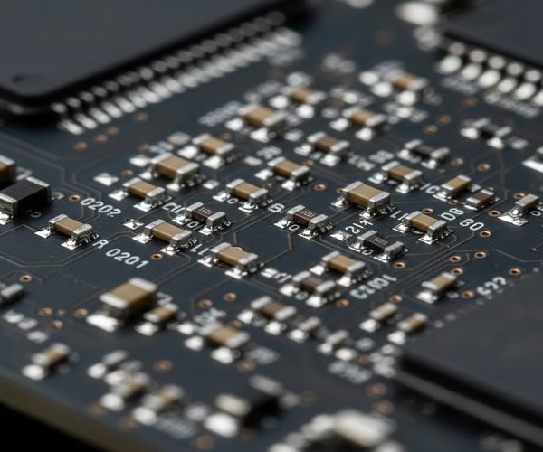
SMD sizes are standardized numerical codes used to define the physical length and width of surface mount electronic components like resistors and capacitors.
You are finalizing a high-stakes PCBA project, the prototypes are due in days, and suddenly your assembly line halts because the 0603 components you ordered are metric 0603 (0201 imperial), making them physically too small for your pads. This “size code trap” is a nightmare for B2B buyers and engineers alike, often leading to scrapped boards and missed market windows. To eliminate these costly errors, this guide to smd sizes will demystify package dimensions and selection strategies.
1. Why are smd sizes so critical for your PCB assembly?
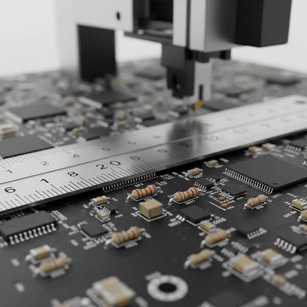
Understanding smd sizes is the foundation of successful manufacturing because these dimensions dictate the solder pad layout and the precision required from SMT pick-and-place machinery. Choosing the wrong package size can lead to tombstoning, poor solder joints, or complete layout failure.
Do you know the difference between Imperial and Metric codes?
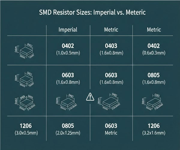
The industry uses two different systems that often share the same numerical names, such as 0603 or 0402. This crossover causes significant confusion for international procurement teams.
- Imperial codes measure dimensions in hundredths of an inch.
- Metric codes measure dimensions in millimeters.
- An 0603 Imperial component is roughly 1.6mm x 0.8mm.
- An 0603 Metric component is actually an 0201 Imperial part.
But wait, there’s more to consider before you hit the “order” button.
How do these codes translate to physical board space?
Smaller codes allow for higher component density, which is vital for modern compact electronics. However, as sizes decrease, the assembly complexity and cost typically increase.
- 01005: The smallest common size for ultra-compact IoT devices.
- 1206: Larger packages often used for power-heavy resistors.
- 0402: The sweet spot for most modern consumer electronics.
Key Takeaway: Correctly identifying whether your BOM specifies Imperial or Metric units prevents catastrophic assembly misfits and component waste.
| Code Type | Typical Length (mm) | Typical Width (mm) | Industry Usage |
| 0402 (Imp) | 1.0 | 0.5 | Most common general-purpose |
| 0603 (Imp) | 1.6 | 0.8 | Hand-solder friendly prototypes |
| 1206 (Imp) | 3.2 | 1.6 | Higher power applications |
Ensuring your supplier understands your specific package requirements is the first step toward a flawless production run.
2. What exactly are the standard smd sizes for resistors?
Standard smd sizes for resistors follow the rectangular package conventions that ensure compatibility across different manufacturers. These standardized footprints allow engineers to swap components without redesigning the entire PCB.
Can you identify the most common resistor footprints?
The most prevalent resistor sizes range from the tiny 0201 to the larger 2512, each serving specific electrical purposes. Smaller resistors are preferred for signal processing, while larger ones handle heat better.
- 0201: Used in smartphones where space is at a premium.
- 0805: Common in industrial controls and legacy designs.
- 2512: Built for high-wattage sensing and power management.
You might be wondering which one is best for your current project.
How does resistor size impact power dissipation?
Physical size is directly linked to a resistor’s ability to dissipate heat safely without failing. A larger surface area allows the component to handle higher power ratings.
- 0402 resistors typically handle 0.063W.
- 0603 resistors usually support up to 0.1W.
- 1206 resistors can handle 0.25W or more.
Key Takeaway: Matching the resistor package to your power requirements is essential for long-term product reliability and safety.
| Resistor Code | Wattage Rating (Typical) | Best Application |
| 0201 | 0.05W | High-density mobile tech |
| 0603 | 0.1W | Standard digital circuits |
| 2512 | 1.0W | Power supplies/Current sensing |
Choosing the right resistor footprint ensures your board stays cool and functional under load.
3. How do capacitor smd sizes differ from resistors?
While they often share the same numerical codes, smd sizes for capacitors must also account for the component’s height and dielectric material. Ceramic capacitors (MLCCs) are the most frequent users of these standard rectangular footprints.
Are capacitor codes identical to resistor codes?
In terms of length and width, yes, they follow the same 0402, 0603, and 0805 naming conventions. However, a capacitor’s height can vary significantly even within the same footprint code.
- Standard height: Matches typical SMT nozzle profiles.
- Low profile: Used for ultra-thin devices like smart cards.
- Extended height: Found in high-capacitance values (e.g., 100uF+).
The plot thickens when you consider the voltage rating.
Why does voltage rating affect capacitor size?
Higher voltage capacitors require thicker dielectric layers, which often forces the component into a larger package. Trying to squeeze a high-voltage cap into a tiny package is a frequent design error.
- Small 0201s: Usually limited to 6.3V or 10V.
- Large 1210s: Can handle 100V or higher in many cases.
- Footprint mismatch: Over-speccing voltage can lead to parts that don’t fit the pads.
Key Takeaway: Always verify the component height and voltage requirements alongside the standard footprint to ensure 100% assembly compatibility.
| Capacitor Size | Typical Height | Voltage Limits | Common Use Case |
| 0402 | 0.5mm | 6.3V – 25V | Decoupling for ICs |
| 1206 | 1.6mm | Up to 100V | Power filtering |
| 1210 | 2.5mm | High Voltage | Automotive/Industrial |
Selecting the right capacitor volume is as much about physics as it is about PCB real estate.
4. How can you compare 0603 vs 0805 smd sizes effectively?
Comparing smd sizes like 0603 and 0805 is a common task for engineers balancing board density against ease of manufacturing. While 0603 has become the modern standard, 0805 remains popular for specific rugged applications.
Is the 0603 package always the better choice?
The 0603 package offers a significant space saving over the 0805, which is crucial for multi-layered, compact designs. However, it requires more precise placement during the SMT process.
- 0603 dimensions: 1.6mm x 0.8mm.
- 0805 dimensions: 2.0mm x 1.25mm.
- Space saving: 0603 uses roughly 50% less area than 0805.
Here is something you might not have considered.
Does the 0805 package offer better reliability?
In high-vibration environments or for hand-built prototypes, the 0805 is often preferred due to its larger solder fillets and physical robustness. It is much easier to rework an 0805 by hand if a field repair is necessary.
- Easier inspection: Joints are more visible to the naked eye.
- Robustness: Better mechanical bond to the PCB.
- Rework: Accessible with standard soldering iron tips.
Key Takeaway: Use 0603 for mass-produced consumer goods, but stick to 0805 for industrial prototypes or products requiring manual maintenance.
| Feature | 0603 Package | 0805 Package | Winner |
| Board Space | 1.28 mm² | 2.50 mm² | 0603 |
| Power (Typ) | 0.1W | 0.125W | 0805 |
| Assembly Cost | Standard | Standard | Tie |
The choice between these two often defines the manufacturing strategy for your entire product line.
5. What are the common smd sizes for discrete semiconductors?
Discrete semiconductors like transistors and diodes use smd sizes that are vastly different from simple resistors, often utilizing the SOT (Small Outline Transistor) naming system. These packages are designed to provide both electrical connectivity and necessary heat sinking.
What does the SOT-23 code represent?
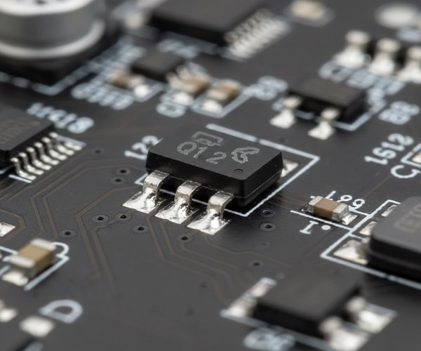
The SOT-23 is perhaps the most famous 3-lead SMD package in the world, used for everything from MOSFETs to voltage regulators. Its three legs allow for stable mounting and clear orientation during assembly.
- Standard SOT-23: Features three leads and a small plastic body.
- SOT-223: A larger version with a thermal pad for higher power.
- SOT-323: A miniaturized version for space-constrained boards.
Think about how this affects your Pick-and-Place speed.
Why are diode packages like SOD-123 so popular?
The SOD (Small Outline Diode) family, such as SOD-123 or SOD-323, provides a two-terminal package that is easy to polarize and place at high speeds. They replace the older, bulky through-hole axial diodes.
- SOD-123: Roughly matches the footprint of a 1206 resistor.
- SOD-323: Smaller footprint for signal-level diodes.
- Flat leads: Improve solder joint reliability during reflow.
Key Takeaway: Semiconductor packages focus on thermal management and lead configuration, making them more complex to select than passive components.
| Package | Lead Count | Common Component | Advantage |
| SOT-23 | 3 | Transistor/MOSFET | Industry standard |
| SOD-123 | 2 | Diode/Zener | Compact & Reliable |
| SOT-223 | 4 | Voltage Regulator | Thermal Dissipation |
Matching the semiconductor package to your thermal dissipation needs is critical for preventing field failures.
6. How do integrated circuits follow smd sizes standards?
Integrated circuits (ICs) use smd sizes that focus on pin pitch and lead shape, such as SOIC, QFP, and BGA packages. As lead counts increase, the industry moves toward “grid array” packages to save space.
What is the difference between SOIC and TSSOP?
Both are “Small Outline” packages with gull-wing leads, but TSSOP is much thinner and has a tighter pin pitch than standard SOIC. This allows for more complex chips in smaller footprints.
- SOIC: 1.27mm pin pitch, easier to solder and inspect.
- TSSOP: 0.65mm pin pitch, requires high-precision SMT.
- Height: TSSOP is significantly lower profile than SOIC.
Wait until you see how BGA changes the game.
Why is BGA the ultimate space-saving SMD size?
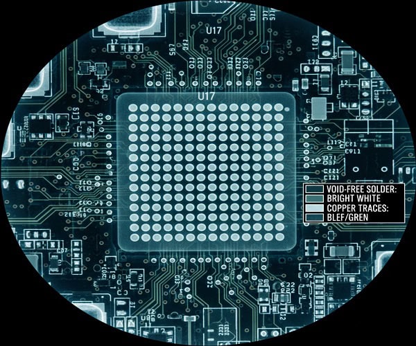
Ball Grid Array (BGA) packages place all connections underneath the chip in a grid of solder balls, allowing for hundreds of pins in a tiny area. This eliminates the need for peripheral leads entirely.
- Highest density: Allows for thousands of connections.
- Hidden joints: Requires X-ray inspection to verify quality.
- Thermal path: The balls provide an excellent path for heat to the PCB.
Key Takeaway: As your IC complexity grows, you must transition to finer pitch packages, which necessitates a more advanced PCBA partner.
| IC Package | Pin Pitch | Lead Type | Inspection Method |
| SOIC | 1.27 mm | Gull-wing | Visual / AOI |
| QFP | 0.5-0.8 mm | Gull-wing | AOI |
| BGA | 0.4-1.0 mm | Solder Ball | X-Ray |
Advanced packaging requires advanced inspection to ensure your complex chips are correctly bonded.
7. How to avoid common smd sizes selection mistakes?
Avoiding mistakes in smd sizes selection requires a rigorous DFM (Design for Manufacturing) review before you finalize your BOM. Even a small clerical error in a part number can lead to components that physically cannot fit your board.
Are you accidentally mixing Imperial and Metric units?
This remains the #1 cause of assembly errors in the electronics industry. A designer might specify an 0603 footprint (Imperial) but the buyer orders 0603 (Metric) parts.
- Verify the datasheet: Check the mm dimensions, not just the code.
- Standardize your library: Use only one system throughout the design.
- BOM double-check: Explicitly state “Imperial” or “Metric” in the BOM.
Could your components be too close together?
Is your component spacing (Clearance) too tight?
If components are placed too close to each other, the SMT nozzles may collide, or solder bridges may form during reflow. Proper clearance is as important as the component size itself.
- Shadowing: Large components can block heat from smaller ones.
- Nozzle access: Ensure there is room for the machine to pick and place.
- Solder masking: Leave enough space for a proper solder mask dam.
Key Takeaway: A thorough DFM check by your assembly partner can catch footprint mismatches before they become expensive production halts.
| Common Mistake | Impact | Prevention |
| Metric/Imp Mix-up | Parts don’t fit pads | Check mm dimensions |
| Insufficient Clearance | Solder bridging/Shorts | Follow DFM guidelines |
| Incorrect Pad Size | Poor solder joints | Use IPC-compliant footprints |
Proactive DFM is the most effective way to ensure your design is actually manufacturable at scale.
8. What is the impact of smd sizes on assembly costs?

The choice of smd sizes significantly impacts your total cost of ownership, from component pricing to the speed of the assembly line. While smaller parts save board space, they can increase the “process cost” of the build.
Do smaller components cost more to assemble?
Yes, ultra-small packages like 01005 or 0.4mm pitch BGAs require slower machine speeds and higher-precision stencils. They also have higher scrap rates due to their sensitivity to process variations.
- Stencil costs: Micro-components need expensive laser-cut stencils.
- Machine time: High-precision placement is often slower.
- Inspection: Small parts may require 100% AOI or X-ray.
Does component size affect the price of the parts themselves?
Why are 0402 and 0603 usually the cheapest options?
These sizes are produced in such massive volumes that they benefit from incredible economies of scale. Moving to either much larger or much smaller packages usually results in a price premium.
- Sweet spot: 0402/0603 are the global volume leaders.
- Obsolescence: Very large SMD parts are becoming “specialty” items.
- Availability: You can find 0603 resistors from dozens of vendors.
Key Takeaway: To minimize costs, stick to 0402 or 0603 packages unless your application’s size or power requirements absolutely dictate otherwise.
| Package Size | Cost per Part | Assembly Difficulty | Overall Value |
| 0603 | Lowest | Low | Excellent |
| 0201 | Medium | High | Good (for IoT) |
| 01005 | Highest | Very High | Specialized |
Balancing component price with assembly efficiency is the secret to a profitable electronics product.
9. How do smd sizes affect PCB thermal management?
In power electronics, smd sizes are chosen specifically for their ability to move heat away from sensitive junctions and into the PCB copper planes. If a component is too small for the current it carries, it will eventually burn out.
Why is the 1206 footprint a favorite for power?
The 1206 footprint provides a large surface area that acts as a mini radiator, allowing for higher power ratings than the more common 0402. It is the “workhorse” for power supply filtering.
- Surface area: More contact with the PCB for cooling.
- Copper weight: Can be paired with thick copper for better thermals.
- Reliability: Less prone to thermal stress cracking.
But what about semiconductors?
How do thermal pads improve semiconductor SMD performance?
Modern SMD power packages, like DPAK or QFN, feature a large metal “thermal pad” on the bottom. This pad must be soldered to a copper pour on the PCB to function correctly.
- Direct path: Heat moves directly from the die to the board.
- Vias: Often requires “thermal vias” to move heat to other layers.
- Efficiency: Allows tiny chips to handle several amps of current.
Key Takeaway: Never sacrifice physical size for space in power-critical circuits; the extra millimeter of “radiator” space is vital for longevity.
| Package Type | Heat Dissipation | Best For |
| 0402 | Very Low | Signal/Logic |
| 1206 | Medium | Power Filtering |
| DPAK/QFN | High | Voltage Regulators |
Thermal design starts with package selection, not just heatsink addition.
10. How to choose the right smd sizes for your next project?
Choosing the right smd sizes requires a holistic view of your product’s lifecycle, from prototyping to mass market. Your choice should balance board size, manufacturing capability, and component availability.
Should you always choose the smallest possible size?
While “smaller is better” is the trend in consumer tech, it isn’t always true for industrial or medical devices where reliability and ease of repair are paramount. If you have the space, slightly larger components can save you money.
- Prototype phase: Use 0805 or 0603 for easier manual tweaks.
- Production phase: Shift to 0402 to reduce board size and cost.
- Medical/Aero: Larger pads can offer better long-term solder joint life.
How do you know if your factory can handle your choice?
Does your PCBA partner have the right equipment for micro-SMDs?
Before finalizing a design using 0201s or fine-pitch BGAs, verify that your assembly house has high-resolution AOI and stable reflow profiles. Not all factories are equipped for ultra-miniature assembly.
- Equipment check: Ask for their minimum component capability.
- Certification: Ensure they follow IPC-A-610 standards.
- DFM service: A good partner will warn you if a size is risky.
Key Takeaway: Consult with your assembly engineer during the design phase to align your component choices with the factory’s optimal process window.
| Project Stage | Recommended Size | Priority |
| Early Prototype | 0805 / 0603 | Debugging Ease |
| Final Beta | 0402 / 0603 | Form Factor |
| Mass Production | 0402 | Cost & Density |
Aligning your design choices with manufacturing reality is the ultimate way to ensure project success.
Conclusion
Mastering smd sizes is the “secret sauce” that separates high-quality, cost-effective electronics from projects plagued by delays and rework. We have explored the critical differences between Imperial and Metric codes, the thermal and power implications of package selection, and the vital role of DFM in avoiding assembly catastrophes. By choosing footprints that balance density with manufacturability, you ensure a smoother path from design to delivery.
At QueenEMS, we specialize in helping B2B partners navigate these complex manufacturing decisions to ensure stable, high-quality production. Whether you are scaling an IoT prototype or managing a complex industrial build, our engineering team is ready to optimize your BOM. Contact us today to discuss your project needs or upload your files for a comprehensive DFM review. Our vision is to empower global innovation through transparent, factory-direct electronics manufacturing excellence.
FAQ
Can I use 0402 components for a hand-soldered prototype?
No, it is generally not recommended unless you have specialized micro-soldering equipment and a steady hand. Most engineers prefer 0805 or 1206 for manual prototyping because they are much easier to handle with standard tweezers and soldering irons.
What’s the best way to prevent Metric and Imperial size confusion?
Yes, the most effective method is to include the physical dimensions in millimeters directly in your BOM and your CAD library. Always explicitly state the measurement system (e.g., “0603 Imperial”) in your procurement documents to avoid any ambiguity with suppliers.
How do I know if my PCBA factory can handle 01005 components?
Start by asking for their equipment list and their “minimum component” specification. High-end factories like QueenEMS use advanced pick-and-place machines and 3D AOI to ensure the precision required for these ultra-miniature packages.
How do I know if a larger SMD package is worth the extra board space?
Yes, if your circuit involves high power (over 0.1W) or high voltage, a larger package like 1206 is often mandatory for safety and thermal stability. In these cases, the reliability gains far outweigh the small increase in PCB real estate.