
PCB component codes are the standardized alphanumeric strings, known as reference designators, used to identify the specific type and location of electronic parts on a circuit board. If you have ever felt overwhelmed by a chaotic Bill of Materials (BOM) or faced delays due to ambiguous labeling, you are not alone. Procurement professionals often struggle with pcb component codes that don’t match the physical board, leading to expensive rework and missed deadlines. This guide demystifies these standards to help you streamline your sourcing and communicate flawlessly with your assembly partners.
What are the most common pcb component codes used today?
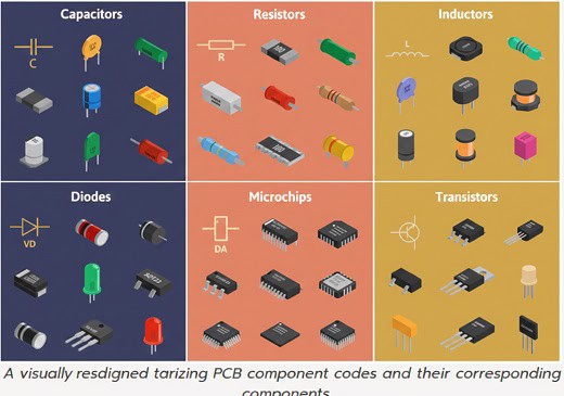
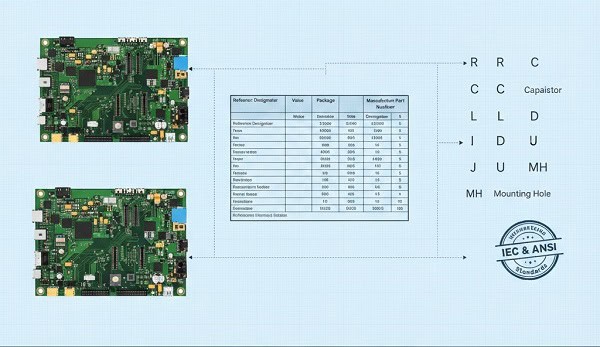
These codes serve as a universal shorthand that tells engineers and automated assembly machines exactly where a part belongs. Using standardized pcb component codes ensures that a “C1” is always recognized as a capacitor and an “R1” as a resistor across global manufacturing floors.
Why do we use standardized abbreviations?
Standardization prevents the “Tower of Babel” effect in electronics manufacturing where different engineers use different terms. By sticking to IEEE or ANSI standards, you ensure your design is readable by any PCB assembly service worldwide.
- R: Resistor
- C: Capacitor
- L: Inductor
- U: Integrated Circuit (IC)
But wait, there’s more to it than just letters.
Key Takeaway: Consistent code usage reduces the risk of human error during manual inspection and automated Pick-and-Place setup.
How do pcb component codes identify passive parts?
Passive components like resistors and capacitors are identified by codes that prioritize their function and numerical sequence. Correctly identifying these pcb component codes is the first step in ensuring your BOM matches your physical layout perfectly.
Can you distinguish between R, C, and L?
Resistors (R), Capacitors (C), and Inductors (L) form the backbone of almost every circuit board you will source. Identifying them correctly allows for faster BOM optimization and prevents procurement teams from ordering the wrong categories of surface-mount devices.
- R1, R2: Sequential resistors
- C1, C2: Sequential capacitors
- L1, L2: Sequential inductors
Here is the kicker.
| Code | Component Type | Primary Function |
| R | Resistor | Limits current flow |
| C | Capacitor | Stores electrical charge |
| L | Inductor | Resists changes in current |
Understanding these basic prefixes allows you to verify the integrity of a parts list at a single glance.
Key Takeaway: Master the “Big Three” (R, C, L) to catch 80% of common clerical errors in early-stage BOM reviews.
Why are pcb component codes for active parts so complex?
Active components require more specific coding because their orientation and pinout are critical to the board’s functionality. When dealing with pcb component codes for transistors (Q) or integrated circuits (U), the margin for error disappears entirely.
How do U and Q codes impact assembly?
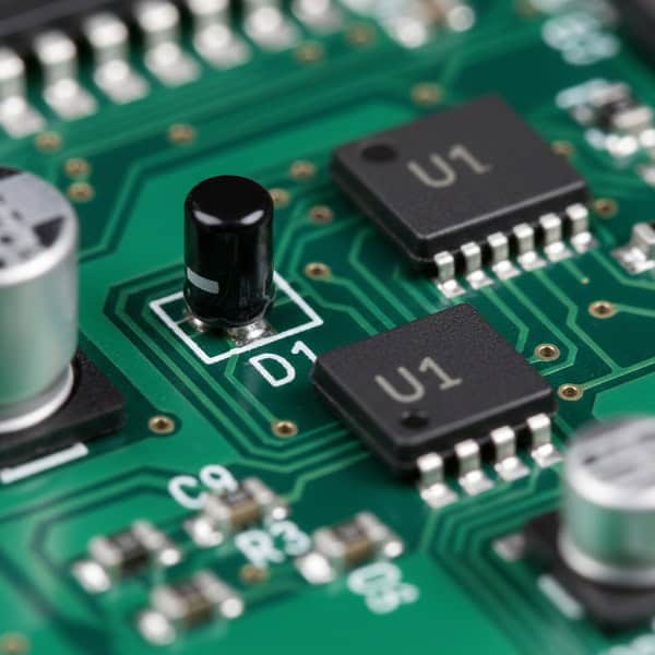
The “U” designation for integrated circuits is perhaps the most critical label on your board. Because these parts often have hundreds of pins, the reference designator must align perfectly with the “pin 1” indicator on the silkscreen to avoid catastrophic failure.
- U: Integrated Circuits (ICs) or Microchips
- Q: Transistors (Bipolar, MOSFET, etc.)
- D: Diodes (including LEDs and Zeners)
You might be wondering how to keep them all straight.
| Prefix | Component | Critical Detail |
| U | IC / SoC | Pin 1 Orientation |
| Q | Transistor | Polarity Matters |
| D | Diode | Anode vs. Cathode |
Ensuring these codes are clear helps your SMT assembly provider set up their machines without constant clarification calls.
Key Takeaway: Active component codes require accompanying polarity markers on the silkscreen to ensure functional assembly.
Can pcb component codes help identify connectors and mechanical parts?
Yes, specialized codes identify the “hardware” of the board, such as headers, jacks, and mounting holes. Managing these pcb component codes properly ensures that your external housing will actually fit the finished electronic assembly.
What are J, JP, and P codes?
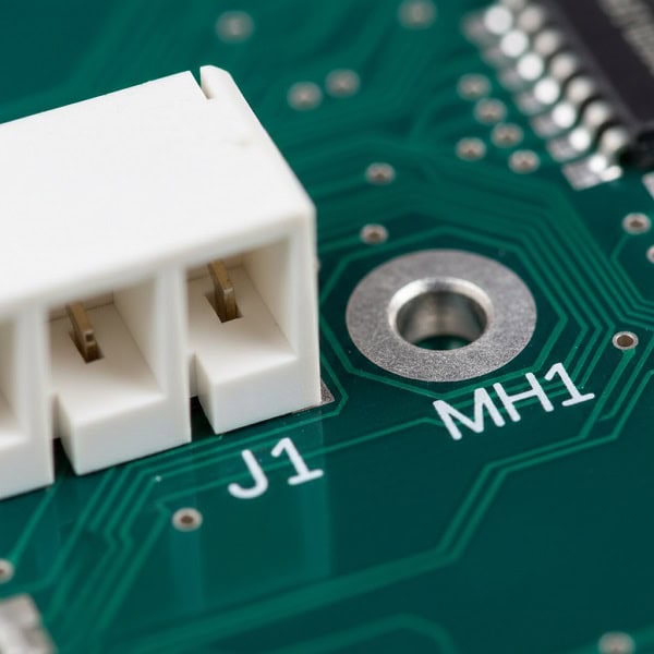
Connectors are typically labeled with “J” (Jack) or “P” (Plug), though many designers use them interchangeably. These labels are vital for the final assembly stage where the board is integrated into a larger system or product casing.
- J: Jacks or Female connectors
- P: Plugs or Male connectors
- H: Headers or Hardware
- MH: Mounting Holes
It gets even more interesting when you look at mechanicals.
| Code | Part Type | Common Usage |
| J | Connector | External Interface |
| JP | Jumper | Configuration Setting |
| MH | Mounting Hole | Chassis Attachment |
Clear mechanical coding prevents assembly technicians from accidentally soldering components into holes intended for screws.
Key Takeaway: Accurate connector coding simplifies the “box build” phase and ensures seamless integration with peripheral cables.
How do pcb component codes manage power and protection devices?
Power-related components use specific codes to alert technicians to high-voltage or sensitive protection areas. Tracking these pcb component codes is a safety requirement for any industrial or consumer electronics project.
Are F and VR codes essential for safety?
Fuses (F) and Voltage Regulators (VR) protect your expensive ICs from power surges or incorrect polarity. If your turnkey PCB assembly lacks clear labeling here, troubleshooting a “dead” board becomes a nightmare for your quality control team.
- F: Fuses
- VR: Voltage Regulators
- T: Transformers
- MOV: Metal Oxide Varistors
Check this out.
| Prefix | Protective Device | Role |
| F | Fuse | Overcurrent Protection |
| VR | Voltage Regulator | Voltage Stability |
| T | Transformer | Voltage Conversion |
These protection codes act as the first line of defense during the board’s initial power-up test.
Key Takeaway: Power codes help testing engineers quickly locate safety components if a board fails its initial functional check.
What role do pcb component codes play in the BOM review?
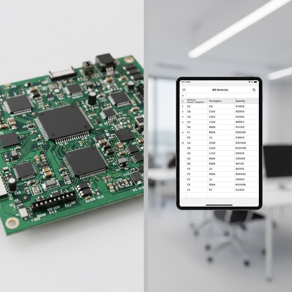
The Bill of Materials (BOM) is a master list where every reference designator must find its match. Without synchronized pcb component codes, your procurement team might buy 100 resistors when the board actually requires 101, halting production.
How do you spot a BOM mismatch?
A mismatch occurs when the reference designators on the PCB layout do not match the quantities or descriptions in the BOM file. Proactive BOM management involves cross-referencing every “C” and “R” to ensure the quantities are perfectly aligned before the order is placed.
- Check for duplicate designators (e.g., two R10s)
- Verify missing numbers in a sequence
- Ensure every code has a corresponding footprint
The real secret to success is simple.
| Audit Step | Action | Benefit |
| Count Check | Match Designators to Quantity | Prevents Shortages |
| Footprint Match | Check Code vs. Pad Size | Avoids Assembly Errors |
| Polarity Check | Verify D/Q/U Orientation | Ensures Functionality |
Auditing these codes before sending them to the factory can save you thousands of dollars in line-down fees.
Key Takeaway: A “clean” BOM, where every component code is accounted for, is the fastest way to get your project through the factory door.
Do pcb component codes change with different international standards?
While most of the world follows the same basic prefixes, slight variations exist between different regional standards. Being aware of how these pcb component codes might vary can help you when sourcing components from international vendors or using global design teams.
Should you use IEEE or Pro Electron?
Most modern designs follow the IEEE 315 standard, which is the gold standard for North American and many Asian manufacturers. However, if you are working with legacy European designs, you might see slight variations in how transistors or specialized diodes are labeled.
- IEEE 315: Common in USA/Asia
- IEC 60617: Common in Europe
- AS 1102: Common in Australia
It’s actually quite straightforward once you see the pattern.
| Component | IEEE (Standard) | IEC (Alternative) |
| Transistor | Q | V or T |
| Integrated Circuit | U | IC or N |
| Diode | D | V |
When in doubt, always include a “Legend” or “Readme” file for your assembly house to clarify which standard you are following.
Key Takeaway: Sticking to the IEEE standard is the safest bet for ensuring your codes are understood by 99% of global PCB factories.
How can pcb component codes reduce sourcing lead times?

When your procurement team understands component codes, they can communicate more effectively with suppliers about alternates and substitutions. Clear pcb component codes allow for rapid identification of which parts are “mission-critical” and which are generic passives.
Can you identify “Generic” vs. “Critical” parts?
Generic parts like “R” and “C” are often easily substituted if the primary manufacturer is out of stock. However, “U” and “Q” codes usually represent specific silicon that cannot be swapped without a significant engineering review.
- R/C/L: High substitutability
- U/Q/D: Low substitutability
- J/P: Mechanical fit required
The faster you identify these, the better.
| Category | Sourcing Strategy | Risk Level |
| Passives (R, C, L) | Use Approved Vendor Lists | Low |
| Actives (U, Q) | Secure Long-Lead Stocks | High |
| Mechanical (J, P) | Verify Physical Samples | Medium |
This level of insight allows procurement to focus their energy on the 20% of parts that cause 80% of the delays.
Key Takeaway: Classifying parts by their codes helps procurement teams prioritize high-risk components during the sourcing phase.
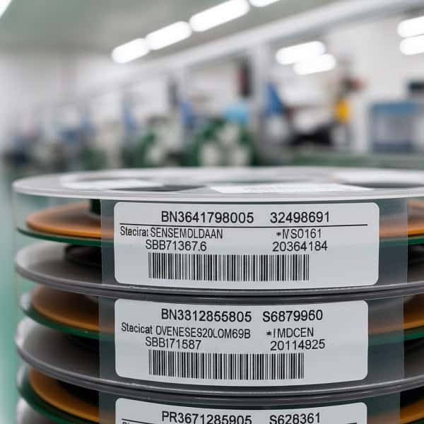
[Image showing a warehouse shelf of electronic components categorized by their reference types]
What are the best practices for labeling pcb component codes on silkscreen?
Legibility is just as important as accuracy when it comes to printing these codes on the physical board. If the pcb component codes are too small or overlapping, the manual inspection team will struggle to verify the assembly.
Is your font size causing assembly errors?
A common mistake in high-density designs is shrinking the reference designator text so much that it becomes a blur of white ink. Ensuring a minimum text height and keeping labels clear of solder pads is essential for a high-yield production run.
- Keep text away from solder pads
- Use a consistent orientation (all 0° or 90°)
- Ensure high contrast against the solder mask
Don’t overlook the obvious.
| Design Rule | Recommendation | Reason |
| Text Height | Min 0.6mm | Human Readability |
| Clearance | 0.2mm from pads | Prevents Solder Issues |
| Placement | Near Pin 1 | Orientation Clarity |
Well-placed labels are the final “quality check” that happens right on the factory floor.
Key Takeaway: Clear silkscreen labeling acts as a map for technicians, reducing the time spent on manual visual inspections.
How do pcb component codes evolve in the era of smart manufacturing?
Modern AI-driven assembly lines use optical character recognition (OCR) to read these codes in real-time. Future-proofing your pcb component codes means designing with machine vision in mind to ensure 100% automated inspection accuracy.
Will machines eventually replace these codes?
While machines use coordinate data (X, Y) for placement, they still use the reference designator as the unique ID for every data log. As we move toward Industry 4.0, these codes will remain the primary link between the digital twin of your board and the physical product.
- Integration with QR codes
- Embedded RFID tracking
- AI-powered BOM cross-referencing
The future looks very efficient.
| Technology | Role of Codes | Impact |
| OCR | Reading Silkscreen | Faster Inspection |
| AI | BOM Verification | Fewer Errors |
| Digital Twin | Mapping Designators | Lifetime Tracking |
Even in a fully automated world, the humble “R1” and “U1” remain the foundation of electronic communication.
Key Takeaway: Designing with clear, standardized codes ensures your project is compatible with the latest automated inspection and smart factory technologies.
Conclusion
Mastering the language of PCB component codes is more than just a technical necessity; it is a strategic advantage for any procurement or production team. By demystifying these labels, you can drastically reduce sourcing errors, speed up your BOM reviews, and foster much clearer communication with your assembly partners. At Queen EMS, we pride ourselves on being more than just a factory; we are your technical collaborators in bringing complex designs to life with precision and speed. If you are ready to experience an assembly process where every “R,” “C,” and “U” is handled with expert care, contact us today to discuss your next project. We don’t just build boards; we build the future of your hardware.
Frequently Asked Questions
Can I use my own custom codes instead of standard reference designators?
Yes, but it is highly discouraged. Standardized codes like R for resistors and C for capacitors are recognized globally by assembly machines and technicians; using custom codes often leads to confusion, higher costs, and significant delays during the assembly process.
What’s the best way to handle multiple components of the same type?
Use sequential numbering based on the component’s position or function. For example, labeling resistors as R1, R2, and R3 in the order they appear on the schematic makes it much easier for both the procurement team and the assembly factory to track quantities and locations.
How do I know if my silkscreen labels are too small?
Check with your PCB manufacturer’s Capability Guide, but a general rule is to keep text height at least 0.6mm. If the text looks cluttered or overlaps with solder pads in your design software, it will likely be unreadable after the printing and soldering process.
What should I do if a component doesn’t fit a standard category?
Use the “U” (Unclassified/IC) or “M” (Miscellaneous) designation and provide a clear description in your BOM. Always include the manufacturer part number and a brief functional description to ensure the sourcing team doesn’t mistake it for a different part type.
How can I verify my BOM matches my PCB component codes?
The most effective way is to perform a “BOM Scrub” using specialized software or a manual cross-check. Ensure that the total count of each reference designator (e.g., how many ‘C’ labels exist) perfectly matches the quantity listed in your procurement spreadsheet.