
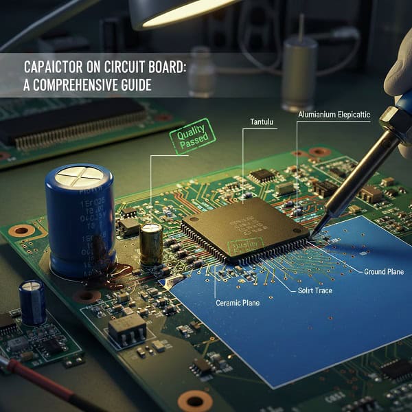
A circuit board capacitor is a passive electronic component designed to store energy in an electric field and regulate voltage within a Printed Circuit Board Assembly (PCBA). You are likely facing a production nightmare where a single bulging or leaking component halts your entire assembly line. This frustration grows when your current supplier cannot explain why these failures happen or how to prevent them in future batches. Here is the deal: we provide high-precision circuit board capacitor integration and sourcing services that eliminate these technical headaches and ensure your hardware remains robust and reliable. With over 100 advanced machines and a dedicated engineering team, QueenEMS offers the professional transparency you need to secure your supply chain.
1. What is the fundamental role of a circuit board capacitor?
A circuit board capacitor serves as a local energy reservoir that stabilizes voltage fluctuations and filters out electronic noise to protect sensitive integrated circuits. You might be wondering how such a simple component can dictate the lifespan of your entire B2B hardware product. By smoothing out power supply ripples, it ensures that high-speed processors receive a clean, steady stream of electricity.
Why is energy storage vital for PCB stability?
Energy storage allows the capacitor to discharge rapidly when the system demands a sudden burst of power. This prevents voltage drops that could lead to logic errors or system resets.
- Acts as a temporary battery for micro-fluctuations.
- Maintains steady current flow during power transitions.
- Prevents data corruption in high-speed digital circuits. Ready for the good part? Proper energy management at the component level reduces the thermal stress on your entire PCBA.
How does noise filtering protect your hardware?
Noise filtering blocks high-frequency interference from entering the signal path of your device. Without this, your sensors or communication modules might produce erratic or incorrect data.
- Decouples the power supply from the signal ground.
- Eliminates electromagnetic interference (EMI) at the source.
- Shields sensitive analog components from digital switching noise.
Key Takeaway: Understanding these roles helps you specify the right performance parameters during the PCBA prototyping phase to avoid costly redesigns.
| Function | Primary Benefit | Common Application |
| Voltage Smoothing | Prevents system resets | Power Supply Units |
| Decoupling | Reduces signal noise | Microprocessor Pins |
| Timing | Controls signal delay | Oscillator Circuits |
| Analysis: Strategic placement of capacitors ensures that voltage-sensitive components remain operational even under erratic power conditions. |
2. Which circuit board capacitor types are best for your design?
Choosing the right circuit board capacitor depends entirely on your specific application requirements such as voltage rating, capacitance value, and physical size. Let’s face it, picking the wrong dielectric material can lead to catastrophic failure in harsh industrial environments. Engineers must balance cost against performance to ensure long-term reliability.
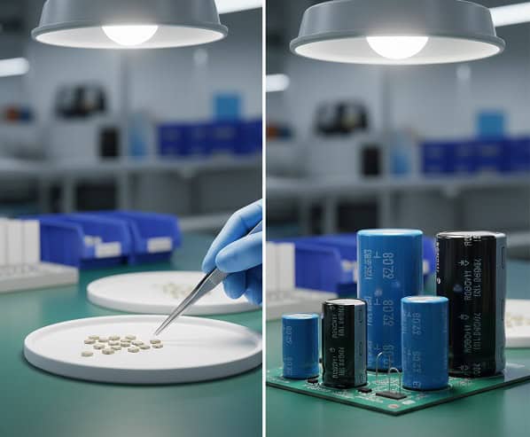
When should you choose ceramic capacitors?
Ceramic capacitors (MLCCs) are the industry standard for high-frequency applications due to their low parasitic inductance and compact surface-mount packages. They are perfect for SMT assembly where space is at a premium.
- Extremely high reliability in small footprints.
- Excellent performance in high-frequency filtering.
- Available in various temperature coefficients like X7R or C0G. This is where it gets interesting: despite their small size, they can handle significant voltage spikes if rated correctly.
What makes electrolytic capacitors essential for power?
Electrolytic capacitors offer much higher capacitance values per unit volume, making them the primary choice for power supply bulk storage. They are often used in THT assembly for their physical robustness.
- Ideal for low-frequency smoothing and energy storage.
- Polarized design requires careful orientation during assembly.
- Cost-effective for high-capacitance requirements.
Key Takeaway: Selecting a mix of ceramic for high-frequency and electrolytic for bulk storage creates a balanced and resilient power delivery network.
| Capacitor Type | Best Use Case | Typical Lifespan |
| Ceramic (MLCC) | High-frequency decoupling | Very High |
| Aluminum Electrolytic | Bulk power filtering | Moderate (Temp dependent) |
| Tantalum | Space-constrained stability | High (Sensitive to surges) |
| Analysis: Comparing these types allows procurement managers to optimize the Bill of Materials for both cost and durability. |
3. How to optimize capacitor placement on circuit board layouts?
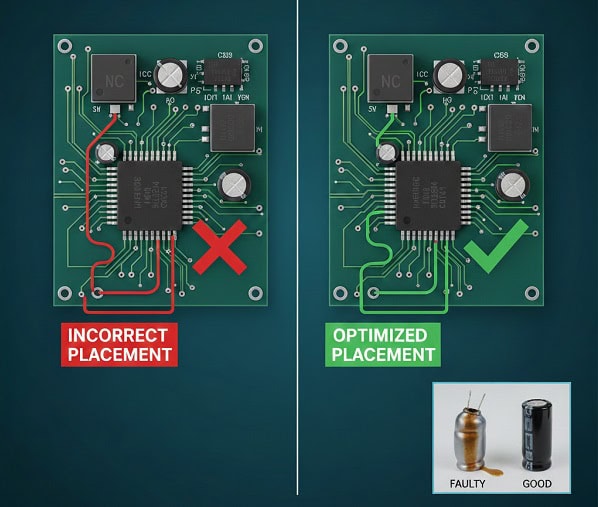
Effective capacitor placement on circuit board designs is the secret to minimizing parasitic inductance and ensuring the highest signal integrity. Here is the deal: even the best capacitor is useless if it is placed too far from the component it is meant to protect. Path resistance and inductance can negate the filtering effects entirely.
Why is proximity to the IC critical?
Placing the decoupling capacitor as close as possible to the power pins of an Integrated Circuit (IC) minimizes the loop area. A smaller loop area directly translates to less electromagnetic interference and better noise suppression.
- Reduces trace inductance between the capacitor and the load.
- Ensures faster response times to high-speed switching needs.
- Minimizes the “ground bounce” effect in digital circuits. But wait, there’s more: using via-in-pad technology can further shorten the electrical path.
How do ground plane connections affect performance?
Direct connections to a solid ground plane provide a low-impedance return path for the current. This is vital for maintaining a clean reference voltage across the entire board.
- Avoids long, inductive traces that pick up noise.
- Improves thermal dissipation for high-power capacitors.
- Enhances the overall EMI shielding of the PCBA.
Key Takeaway: Following strict placement rules during the design phase ensures that your mixed assembly remains stable across all operating frequencies.
| Placement Rule | Technical Goal | Impact on Yield |
| Near IC Power Pins | Minimize loop inductance | High |
| Symmetrical Layout | Even thermal distribution | Medium |
| Shared Ground Vias | Reduce board complexity | Low |
| Analysis: Proper placement is a non-negotiable step for achieving regulatory compliance in telecom or industrial electronics. |
4. What are the common faulty capacitor symptoms in PCBA?
Identifying faulty capacitor symptoms early can save your company thousands of dollars in warranty claims and field repairs. Believe it or not, most electronic failures in the field are traced back to a single degraded capacitor that was overlooked. Recognizing the physical and electrical red flags is a mandatory skill for any quality manager.
How can you spot physical degradation?
Physical signs like bulging tops, leaking electrolyte, or discolored casings are clear indicators that a capacitor has reached the end of its life. These issues often stem from excessive heat or poor manufacturing quality.
- Look for “doming” on the top of aluminum cans.
- Identify crusty residue around the base of the component.
- Check for thermal scorching on the surrounding PCB substrate. What is the catch? Sometimes a capacitor looks perfect but has completely lost its electrical properties.
What are the electrical signs of failure?
Electrical symptoms include erratic system reboots, excessive power supply noise, or a complete failure to power on. You might notice that your device works fine when cold but fails as soon as it reaches operating temperature.
- Increased Equivalent Series Resistance (ESR) leading to heat.
- Loss of capacitance causing unstable voltage rails.
- Short circuits that trigger overcurrent protection in the PSU.
Key Takeaway: Regular inspection and the use of high-quality components from a reliable PCBA factory drastically reduce these failure rates.
| Symptom | Probable Cause | Urgent Action |
| Bulging/Swelling | Overvoltage or overheating | Immediate Replacement |
| System Instability | High ESR or low capacitance | Technical Diagnosis |
| Burning Smell | Dielectric breakdown/Short | Power Down Immediately |
| Analysis: Monitoring these symptoms allows for proactive maintenance rather than reactive crisis management. |
5. How to replace capacitor on PCB safely and professionally?
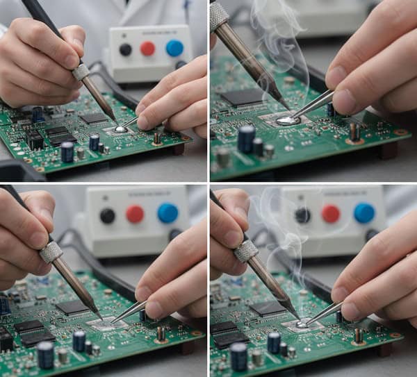
Learning how to replace capacitor on PCB units is an essential skill for repairing prototypes or extending the life of industrial equipment. The truth is, improper desoldering techniques can easily lift pads or damage neighboring fine-pitch components. You need the right tools and a steady hand to ensure the board remains functional after the repair.
What tools are required for a professional repair?
A temperature-controlled soldering station, high-quality flux, and a desoldering pump or wick are the bare minimum requirements. For multi-layer boards, a pre-heating plate is often necessary to prevent thermal shock.
- Use a chisel tip for better heat transfer on large pads.
- Apply fresh solder to old joints to help them flow.
- Ensure the polarity of the new component matches the board marking. Now, this is important: always verify the voltage rating of the replacement is equal to or higher than the original.
How do you avoid damaging the PCB traces?
Excessive heat is the enemy of PCB copper traces. By applying heat only long enough to melt the solder, you protect the adhesive bond between the copper and the FR4 substrate.
- Clean the area thoroughly with isopropyl alcohol after soldering.
- Avoid pulling on the component until the solder is fully liquid.
- Use a thermal bridge if working near heat-sensitive sensors.
Key Takeaway: Mastering the repair process allows your team to salvage expensive BGA assembly boards that would otherwise be scrapped.
| Repair Step | Best Tool | Safety Tip |
| Solder Removal | Desoldering Pump/Wick | Wear Eye Protection |
| Component Cleaning | Isopropyl Alcohol | Ensure Well-Ventilated Area |
| New Installation | Soldering Iron (350°C) | Verify Component Polarity |
| Analysis: A methodical approach to replacement ensures the integrity of the board’s electrical circuits is maintained. |
6. How do voltage and temperature ratings affect circuit board capacitor selection?
When selecting a circuit board capacitor, the voltage and temperature ratings are the most critical factors for long-term survival in B2B applications. You might think that a 16V capacitor is fine for a 12V rail, but in the world of industrial electronics, that margin is often too slim. Engineering for the “worst-case scenario” is what separates professional products from hobbyist builds.
Why is voltage derating necessary?
Voltage derating involves choosing a capacitor with a significantly higher voltage rating than the actual operating voltage. This provides a safety buffer against power surges and reduces the stress on the dielectric material.
- Standard practice suggests at least 20-50% headroom.
- Prevents dielectric breakdown during unexpected spikes.
- Extends the operational life of the component significantly. Ready for the good part? Higher voltage ratings often come with lower ESR, which improves efficiency.
How does ambient temperature impact longevity?
Capacitors, especially electrolytic ones, have a lifespan that is highly dependent on temperature. For every 10°C increase in operating temperature, the expected life of an electrolytic capacitor is roughly cut in half.
- Choose 105°C rated components for industrial or automotive use.
- Ensure proper airflow around bulk capacitors in power stages.
- Consider the self-heating effect caused by ripple current.
Key Takeaway: Investing in higher-rated components during the manufacturing process ensures your product thrives in demanding environments like EV charging or outdoor telecom.
| Parameter | Recommended Margin | Application Example |
| Voltage Rating | +50% of Operating Voltage | DC-DC Converters |
| Temperature | +20°C above Max Ambient | Industrial Automation |
| Ripple Current | 1.5x expected load | Motor Controllers |
| Analysis: Proper specification prevents premature aging and reduces the total cost of ownership for your customers. |
7. What are the key considerations for capacitor selection for PCB design?
Effective capacitor selection for PCB design requires a deep understanding of both the electrical environment and the mechanical constraints of the housing. Here is the deal: if you only look at capacitance and voltage, you are missing half the picture. Factors like ESR, ESL, and aging characteristics will dictate how your circuit behaves after three years in the field.
How does ESR impact your power efficiency?
Equivalent Series Resistance (ESR) represents the internal losses of a capacitor. High ESR leads to internal heating and voltage drops, which can be devastating for high-current applications like robotics or power tools.
- Lower ESR improves the efficiency of switching regulators.
- Reduces the heat generated within the component body.
- Enables better ripple current handling in power filters. What is the real story? Sometimes using multiple smaller capacitors in parallel is better than one large one to lower total ESR.
Why does the dielectric material matter?
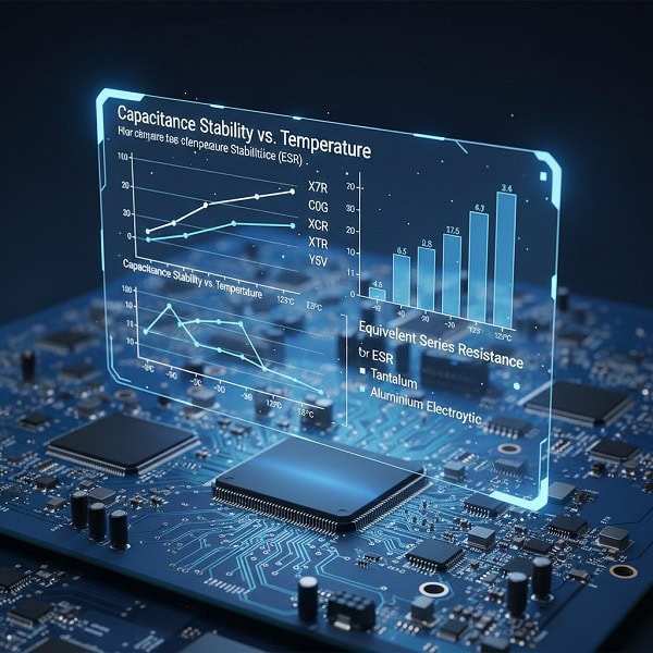
The choice of dielectric affects how the capacitance changes with temperature and voltage. For example, Class 2 ceramics like Y5V lose significant capacitance as they heat up, whereas C0G remains stable.
- Choose stable dielectrics for timing and oscillator circuits.
- Use high-K dielectrics for general decoupling where space is limited.
- Understand the “DC bias effect” where voltage reduces capacitance in MLCCs.
Key Takeaway: Balancing these technical trade-offs during the IC programming and testing phase leads to a more predictable and robust product performance.
| Dielectric Material | Stability | Common Use |
| C0G / NP0 | Excellent | Precision Timing |
| X7R | Good | General Coupling |
| X5R | Fair | Consumer Electronics |
| Analysis: Matching the dielectric to the application prevents unexpected circuit behavior across different temperature ranges. |
8. How do capacitors handle high-frequency noise in telecom?
In the fast-paced world of telecom, a circuit board capacitor must perform at frequencies reaching into the gigahertz range. You might be wondering how a component with physical leads can possibly stay effective at such speeds. The answer lies in the parasitic elements—inductance and resistance—that become dominant as the frequency increases.
What is the self-resonant frequency (SRF)?
The SRF is the point where a capacitor’s internal inductance cancels out its capacitance. Above this frequency, the component actually starts behaving like an inductor, losing its ability to filter noise.
- Smaller package sizes typically have higher SRF.
- Critical for 5G and high-speed data transmission designs.
- Requires careful simulation during the PCB layout stage. This is where it gets interesting: choosing the wrong package size can render your noise filter completely invisible to high-frequency signals.
How to implement multi-stage filtering?
Using different types and values of capacitors in a “decoupling network” allows for broad-spectrum noise suppression. This ensures that both low-frequency ripples and high-frequency spikes are effectively mitigated.
- Combines large electrolytic for bulk and small ceramic for high-speed.
- Utilizes ferrite beads in conjunction with capacitors for EMI.
- Prevents cross-talk between high-speed digital lanes.
Key Takeaway: High-frequency excellence is essential for maintaining signal integrity in modern drone and communication technology.
| Frequency Range | Capacitor Choice | Design Strategy |
| < 1 MHz | Electrolytic | Bulk storage |
| 1 MHz – 100 MHz | X7R Ceramic | General Decoupling |
| > 100 MHz | C0G Ceramic (0201) | High-speed bypass |
| Analysis: A multi-tiered approach to filtering is the industry standard for high-performance communication hardware. |
9. Why is capacitor quality critical for consumer electronics?
For high-volume consumer electronics, the reliability of every circuit board capacitor directly impacts your brand’s reputation and bottom line. Let’s face it, a single batch of low-quality components can lead to a massive product recall. In the B2B world, consistency and traceability are the only ways to mitigate this risk.
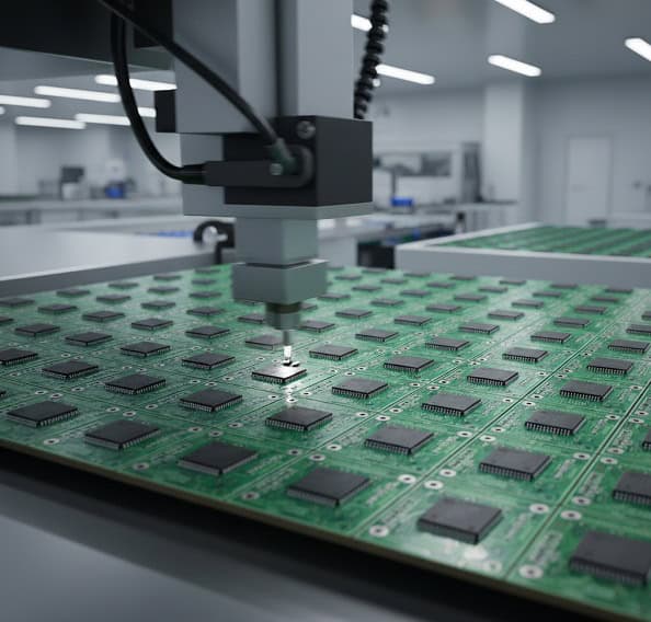
How does manufacturing quality affect yield?
Automated optical inspection (AOI) and X-ray testing are necessary to ensure that every capacitor is soldered correctly. Solder bridges or tombstoning on tiny MLCCs can lead to immediate or latent failures in the field.
- Ensures consistent soldering for millions of units.
- Detects internal cracks in ceramic capacitors caused by thermal stress.
- Validates the correct orientation of polarized components. But wait, there’s more: high-quality sourcing prevents the use of counterfeit components that lack proper ratings.
What role does environmental compliance play?
In many markets, capacitors must meet strict RoHS and REACH standards to be legally sold. Ensuring your supplier provides authentic certifications is a mandatory step for any purchasing manager.
- Guarantees the absence of lead and other hazardous substances.
- Simplifies international logistics and customs clearance.
- Aligns your brand with global sustainability initiatives.
Key Takeaway: Partnering with an experienced factory like QueenEMS ensures that your high-volume production meets both quality and regulatory standards.
| Quality Metric | Importance | Verification Method |
| Solder Joint Integrity | Very High | AOI / X-Ray |
| Component Traceability | High | Batch Code Verification |
| RoHS Compliance | Mandatory | Certification Audit |
| Analysis: Rigorous quality control at the factory level is the most effective way to protect your market share. |
10. How to source reliable capacitors for industrial automation?
Sourcing the right circuit board capacitor for industry automation requires a supplier who understands the demands of 24/7 operation. Here is the deal: industrial environments are plagued by electrical noise, heat, and vibration. You need a partner who can provide not just parts, but engineering-driven solutions that keep your machines running.
What should you look for in a PCBA partner?
A reliable partner offers more than just assembly; they provide Design for Manufacturability (DFM) reviews to catch component errors before production starts. This proactive approach saves time and prevents wasted materials.
- Fast response times for BOM clarifications.
- Transparent component sourcing with full traceability.
- Expertise in both SMT and THT for rugged industrial boards. What is the real story? A factory that understands your business model will prioritize your deadlines and quality requirements over simple cost-cutting.
How to manage long-term component availability?
Industrial products often have a lifespan of 10 years or more. Choosing capacitors from reputable manufacturers with long-term support plans prevents your product from becoming obsolete due to a single “end-of-life” component.
- Identify “at-risk” components during the design phase.
- Secure buffer stocks for critical high-value capacitors.
- Plan for drop-in replacements in case of supply chain disruptions.
Key Takeaway: Strategic sourcing and professional PCBA services transform your supply chain into a competitive advantage.
| Sourcing Factor | Industrial Need | Supplier Requirement |
| Reliability | 24/7 Operation | 100% Functional Testing |
| Longevity | 10+ Year Lifecycle | Obsolescence Management |
| Support | Technical Clarity | Engineering-Led Sales |
| Analysis: Long-term success in industrial sectors depends on the stability of your component supply and assembly quality. |
Final Thoughts on PCB Capacitors
We have covered everything from the fundamental roles of energy storage to the complex requirements of high-frequency telecom designs. Selecting and integrating the right circuit board capacitor is not just a technical necessity—it is a strategic move to ensure your product’s success in a competitive market. By focusing on quality, placement, and proper sourcing, you eliminate the risks of system failure and costly repairs. Contact us today to discuss how our professional PCBA services can streamline your production. Our mission is to transform your complex electronic designs into reliable, market-ready products with unmatched efficiency and transparency.
FAQ Section
Q1: Can I use a capacitor with a higher voltage rating than the original? Yes, it is generally safe and often recommended. A higher voltage rating provides a larger safety margin and can even extend the component’s life, as long as the physical size fits the PCB footprint.
Q2: How do I know if a ceramic capacitor is cracked without an X-ray? It is difficult. While some cracks are visible under high magnification, internal micro-cracks often require electrical testing or X-ray inspection. If a board has been dropped or flexed, it is best to replace the MLCCs in that area.
Q3: What’s the best way to determine the polarity of an electrolytic capacitor? Look at the casing. Most radial electrolytic capacitors have a stripe (usually white) indicating the negative lead. On the PCB, the positive pad is often marked with a “+” sign or a square-shaped pad rather than a round one.
Q4: How do I know if my capacitor choice is suitable for high-vibration environments? Check the mounting style. For high vibration, use through-hole components with additional adhesive or surface-mount capacitors with flexible terminations (soft-term) to prevent solder joint cracking.
Q5: Can I replace a tantalum capacitor with an aluminum one? Rarely. Tantalum capacitors have much lower ESR and better frequency response. Replacing them with a standard aluminum electrolytic may cause circuit instability or excessive noise unless you use a specialized low-ESR polymer version.