

Quick Answer: To qualify a ceramic PCB for automotive use, you must validate the substrate against AEC-Q200 thermal cycling methodologies, specifically proving it survives 1,000 to 3,000 cycles from -40°C to +150°C without delamination. You cannot rely on a supplier’s generic certificate; you must secure lot-specific test data including destructive physical analysis (DPA), peel strength curves, and insulation resistance data to pass your Tier-1 PPAP audit.
Key takeaways:
- AEC-Q200 itself has no certification body; qualification requires supplier self-declaration backed by your own PPAP acceptance.
- Automotive thermal cycling mandates -40°C to +150°C for 1,000+ cycles, while standard industrial tests often stop at 500 cycles.
- Skipping Destructive Physical Analysis (DPA) to save a $500 lab fee risks multi-million dollar field failure recalls.
- Your supplier qualification file is invalid if the thermal cycling report is older than 12 months or disconnected from your production batch.
Table of Contents
- Why Automotive Ceramic PCBs Face a Higher Qualification Bar Than Industrial Boards?
- What Standards Apply to Automotive Ceramic PCBs — AEC-Q200 and Beyond?
- What Thermal Cycling Test Does Automotive Certification Require?
- What Is DPA (Destructive Physical Analysis) and Why Skipping It Is Catastrophic?
- What Test Data Should You Demand From Your Ceramic PCB Supplier?
- How to Design a Test Coupon That Validates Your Ceramic Substrate Early?
- What Medical and Aerospace Ceramic PCB Standards Overlap With Automotive?
- How to Build a Qualification File That Survives a Tier-1 Automotive Audit?
- What Are the Most Frequently Asked Questions About Automotive Ceramic Qualification?
Are you struggling to get your new EV on-board charger substrate approved by a Tier-1 auditor? Many engineers submit supplier packages only to hit a wall when procurement rejects outdated, generic thermal test reports. Transitioning from industrial components to automotive-grade requires strict, lot-traceable validation. At QueenEMS, we maintain a 99.7% first-pass yield rate because we structure our automotive testing to anticipate the exact data your PPAP demands before you even submit it.
Why Automotive Ceramic PCBs Face a Higher Qualification Bar Than Industrial Boards?
An automotive ceramic PCB qualification requires proving the board can survive a minimum of 1,000 extreme thermal shocks (-40°C to +150°C), whereas a standard industrial board often only needs to survive 500 cycles at a lower maximum temperature of 125°C. This massive jump in mechanical stress testing is mandatory because automotive environments mix high vibration with violent temperature swings under the hood, easily tearing apart weak copper-to-ceramic bonds.
What changes when you upgrade? When shifting from industrial to automotive specifications, you must tighten your manufacturing tolerances. Copper layer thickness variations must stay within ±10%, pad spacing requires wider clearance to handle higher voltages, and surface finishes must survive harsher environmental exposures. To understand how we control these variables, review our automotive ceramic PCB manufacturing parameters.
- Industrial targets: 500 thermal cycles, 125°C max junction temperature.
- Automotive Tier-2 targets: 1,000 thermal cycles, 150°C max junction temperature.
- Automotive Tier-1 (EV) targets: 1,500 to 3,000 thermal cycles, 175°C max junction temperature.
Bottom line: Do not attempt to use an industrial-grade substrate in a vehicle; you must specify an automotive-grade build that strictly dictates copper thickness tolerances and forces extended thermal shock validation.
What Standards Apply to Automotive Ceramic PCBs — AEC-Q200 and Beyond?
To achieve ceramic PCB automotive qualification, you must utilize the testing methodology of AEC-Q200 Rev E, combined with the manufacturing acceptance criteria of IPC-6012 Class 3. IPC-6012 Class 3 dictates the physical build parameters (like an annular ring minimum of ≥ 0.05 mm), while AEC-Q200 provides the framework for environmental stress testing.
Many engineers misinterpret AEC-Q200. According to the official Automotive Electronics Council (aecouncil.com), “There are no certifications for AEC-Q200 qualification and there is no certification board run by AEC to qualify components.” This means the burden falls on you. AEC-Q200 is a supplier self-declaration. You do not get a “certificate”; instead, you validate the supplier’s test data through your own Production Part Approval Process (PPAP).
- AEC-Q200 provides the thermal cycling framework (-40°C to +150°C).
- IPC-6012 Class 3 dictates the high-reliability manufacturing tolerances.
- PPAP is the actual mechanism you use to approve the substrate for the vehicle.
| Standard / Level | Target Application | Key Environmental Test | Certification Body |
|---|---|---|---|
| AEC-Q200 | Automotive Passive/Substrates | -40°C to +150°C (1000+ cycles) | None (Self-declared + PPAP) |
| IPC-6012 Class 3 | High-Reliability Electronics | Physical build tolerances | IPC |
| MIL-STD-883 | Military / Aerospace | -55°C to +125°C (Liquid shock) | DLA (Defense Logistics Agency) |
| ISO 10993 | Medical Implants | Cytotoxicity / Sensitization | FDA / Notified Bodies |
Choose AEC-Q200 methodology if you are building automotive power modules. Choose IPC-6012 Class 3 as your baseline manufacturing standard regardless of the specific high-reliability industry.
Bottom line: Stop asking suppliers for an “AEC-Q200 Certificate” and start demanding the raw, lot-specific thermal cycling test data that proves they followed the methodology.
What Thermal Cycling Test Does Automotive Certification Require?
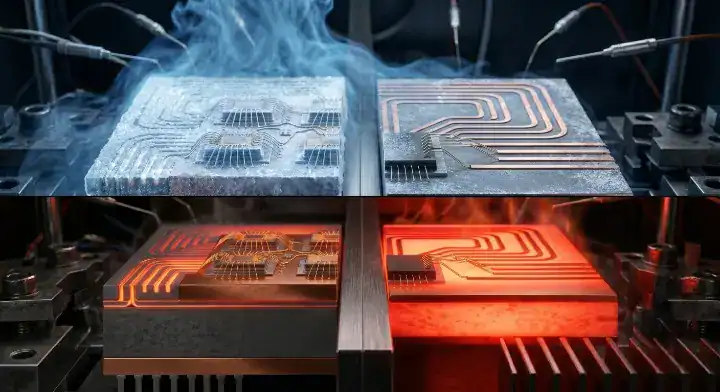
A proper ceramic PCB automotive qualification requires a thermal cycling test (TCT) where the substrate transitions from -40°C to +150°C for 1,000 consecutive cycles, holding at each temperature extreme for 15 minutes. The ramp rate between these temperatures must be carefully controlled at ≤ 15°C/minute to simulate realistic harsh field conditions without inducing artificial thermal shock.
Why is this specific profile mandatory? EV traction inverters and on-board chargers generate massive internal heat while operating in freezing external environments. The differing Coefficient of Thermal Expansion (CTE) between the copper traces and the ceramic base forces the board to warp and flex. If the bonding interface is weak, the copper will delaminate long before the 1,000-cycle mark. We see this frequently in advanced EV power electronics assembly, where thermal management dictates the lifespan of the entire system.
- Industrial TCT: Typically stops at 500 cycles up to 125°C.
- Automotive Tier-2 TCT: Mandates 1,000 cycles from -40°C to 150°C.
- EV Tier-1 TCT: Pushes the boundary to 1,500–3,000 cycles at 175°C.
| Parameter | Industrial Grade | Automotive Tier-2 | Automotive Tier-1 (EV) | Military (MIL-STD-883) |
|---|---|---|---|---|
| Temperature Range | -40°C to +125°C | -40°C to +150°C | -40°C to +175°C | -55°C to +125°C |
| Required Cycles | 500 | 1,000 | 1,500 – 3,000 | 10 – 100 |
| Transfer Medium | Air to Air | Air to Air | Air to Air | Liquid to Liquid |
| Dwell Time | 10 minutes | 15 minutes | 15–30 minutes | 5 minutes |
Choose the 1,000-cycle Tier-2 test if you are building standard automotive electronics. Choose the 3,000-cycle Tier-1 test if you are designing silicon carbide (SiC) modules for 800V EV architectures.
Bottom line: Your thermal cycling test must specifically match the 15-minute dwell time and ≤ 15°C/minute ramp rate to be accepted by an automotive OEM auditor.
What Is DPA (Destructive Physical Analysis) and Why Skipping It Is Catastrophic?
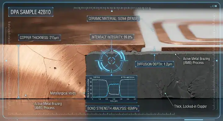
DPA (Destructive Physical Analysis) is a mandatory test for ceramic PCB automotive qualification that involves physically cutting open 3 to 5 sample boards per batch to inspect the copper-ceramic interface for micro-voids and cracks under high magnification. Unlike Automated Optical Inspection (AOI) or standard X-ray, DPA physically exposes internal metallurgical failures that are completely invisible from the outside.
Engineers on Stack Exchange often ask: “DPA is destructive and ruins good boards. We only have a small prototype batch—can we skip it?” We face this scenario often: An automotive Tier-2 client asked us to help them qualify a ceramic substrate supplier for an EV on-board charger. The supplier’s sample boards looked perfect on AOI and X-ray. The client wanted to skip DPA to save 3 boards from their 15-piece sample lot. We insisted on DPA. The cross-section analysis revealed micro-voids at the copper-Al₂O₃ interface at 4 of the 6 sampled locations — voids that X-ray couldn’t detect because they were under 50 μm in diameter. Under thermal cycling, those voids would propagate and cause delamination by cycle 600, well short of the 1,500-cycle requirement. We switched to a different supplier immediately. The DPA cost: 3 boards and $400 in lab fees. The alternative: a supplier qualification failure caught after PPAP submission, resulting in an 8-week delay.
- Automotive DPA Requirement: Cut and inspect a minimum of 3 boards per production batch.
- Military DPA Requirement: Cut and inspect a minimum of 5 boards per production batch.
- What it finds: Micro-voids, interface delamination, and latent stress cracks.
| Action Taken | Upfront Cost | Field Failure Risk | Total Project Cost Impact |
|---|---|---|---|
| Perform DPA on 3 boards | $500 (Lab fee + destroyed boards) | Near 0% | $500 |
| Skip DPA (Rely on X-ray) | $0 | High (Micro-voids remain hidden) | $50,000+ (PPAP rejection + delay) |
| Skip DPA (Mass Production) | $0 | Extreme | $5,000,000+ (Vehicle recall) |
Choose to perform DPA on every single batch if your board controls safety-critical automotive systems. Avoid skipping DPA just to save a few prototype boards, as the hidden voids will inevitably cause field failures.
Bottom line: Treat Destructive Physical Analysis as a non-negotiable insurance policy; X-ray simply cannot resolve the microscopic interface voids that destroy automotive boards.
What Test Data Should You Demand From Your Ceramic PCB Supplier?
To pass a ceramic PCB automotive qualification PPAP Level 3 audit, you must demand lot-specific data from your supplier including a thermal cycling report (1000+ cycles), a peel strength pull curve (≥ IPC minimums), and insulation resistance test results (≥ 100 MΩ at 500V). The critical factor is that every single document must carry the exact same lot number as the boards you are physically receiving.
We see this breakdown constantly on forums like Reddit’s r/PrintedCircuitBoard: “We need to submit PPAP, but our supplier gave us a thermal cycling report from 2022. The Tier-1 buyer rejected it. What do we actually need?” Here is what happens on the factory floor: We review supplier qualification packages for clients regularly. The most common gap is lot traceability. A supplier sends a thermal report from 2022 — but their raw material source changed in 2023, their furnace was upgraded in early 2024, and they switched copper foil suppliers late last year. That 2022 report is completely meaningless. Roughly 40% of first-time automotive suppliers cannot provide lot-specific data because they have never been forced to. We require four items for PPAP: (1) a thermal report dated within 12 months, (2) tied to the current production lot, (3) real peel strength pull curves, and (4) DPA cross-section photos. Without all four, the supplier is disqualified.
- Requirement 1: Thermal cycling report directly traceable to the current batch lot number.
- Requirement 2: Peel strength data showing the actual N/mm force curve, not just a “Pass/Fail” checkmark.
- Requirement 3: Cross-section micrographs from the DPA test showing a clean bonding interface.
| Document Required | Acceptable Format | Red Flag (Do Not Accept) |
|---|---|---|
| Thermal Cycling Report | Dated within 12 months, exact lot number | Report is 2+ years old, generic part number |
| Peel Strength Data | Graph showing force curve over time (N/mm) | Simple spreadsheet saying “Pass” |
| Cross-Section Analysis | High-res micrograph photos at 3+ locations | Text-only description without photos |
Demand lot-specific testing if you are submitting a Level 3 PPAP to an OEM. Reject any supplier that tries to hand you a generic “company-wide” certification document from years ago.
Bottom line: If your supplier cannot produce a fresh thermal cycling report linked to your exact production lot number, you cannot use them for an automotive project.
How to Design a Test Coupon That Validates Your Ceramic Substrate Early?
A test coupon for ceramic PCB automotive qualification is a small, sacrificial 10mm × 10mm copper trace pattern placed on the edge of your production panel that undergoes thermal cycling to validate the batch without destroying your expensive main boards. By designing this coupon directly into the manufacturing gerbers, you create an independent validation tool that proves process stability.
Why is this a smart strategy? Instead of pulling functional, fully-routed boards off the line for destructive testing, the factory breaks off the coupon. You place 4 specific thermal monitoring points on this coupon to track resistance changes. If the copper begins to delaminate during the 1,000-cycle test, the resistance on the coupon spikes, giving you early warning before you populate thousands of dollars of silicon carbide chips onto a doomed batch. Taking advantage of a free engineering review helps ensure your coupon is positioned correctly on the panel array.
- Add a 10mm × 10mm square of your thickest copper to the panel frame.
- Route a daisy-chain trace through the coupon to measure continuous resistance.
- Use the coupon for the mandatory DPA cross-section analysis.
Bottom line: Add a dedicated thermal test coupon to your panel frame; it acts as a cheap, early-warning system that saves you from assembling defective ceramic substrates.
What Medical and Aerospace Ceramic PCB Standards Overlap With Automotive?
While ceramic PCB automotive qualification relies heavily on thermal cycling, medical applications pivot to ISO 10993 for biocompatibility, and aerospace shifts to MIL-STD-883 for violent liquid-to-liquid thermal shock. Understanding these overlaps is critical if you are trying to source substrates from a factory that primarily serves a different high-reliability sector.
If you are evaluating a medical supplier for an automotive project, be cautious. A supplier building implantable devices under ISO 10993 focuses obsessively on cytotoxicity (ensuring the ceramic doesn’t poison human tissue) but may have zero experience with the 1,500-cycle thermal fatigue required by a car’s inverter. Conversely, a military supplier used to MIL-STD-883 tests their boards by plunging them into freezing liquid—a severe shock, but usually only for 10 to 100 cycles, which doesn’t prove the long-term wear-out fatigue an EV faces over 10 years. We navigate these cross-industry requirements daily during medical-grade PCB assembly.
- Medical (ISO 10993): Focuses on cytotoxicity, sensitization, and biological safety.
- Aerospace (MIL-STD-883): Focuses on rapid liquid-based thermal shock and extreme vibration.
- Automotive (AEC-Q200): Focuses on long-term air-based thermal fatigue (1,000+ cycles).
Bottom line: Do not assume a supplier is qualified for automotive just because they build medical or military boards; the specific thermal fatigue mechanics are completely different.

How to Build a Qualification File That Survives a Tier-1 Automotive Audit?
To build a flawless ceramic PCB automotive qualification file, you must compile a PPAP package that links the supplier’s raw material certificates, the batch-specific thermal cycling results, the DPA micrographs, and the final electrical test data into a single, unbroken chain of traceability. The Tier-1 auditor is not just looking for good test results; they are hunting for gaps in your documentation chain.
Here is the strategy: Start at the end. When you know the auditor requires proof of interface integrity, you mandate the DPA test upfront. When you know they need batch verification, you force the supplier to use lot numbers on every single PDF. If you are unsure how to pressure a factory into providing this data, read our guide on how to evaluate a ceramic PCB manufacturer to learn the exact questions to ask during the initial RFQ phase.
- Link raw material lot numbers (ceramic powder, copper foil) to the bare board lot number.
- Attach the 12-month thermal cycling report to that specific board lot.
- Include the 3-point DPA cross-section photos.
- Provide the final insulation resistance (IR) test data.
Bottom line: A Tier-1 auditor will reject your PPAP if your documentation lacks lot traceability, even if the physical ceramic boards are manufactured perfectly.
What Are the Most Frequently Asked Questions About Automotive Ceramic Qualification?
Does AEC-Q200 certification apply to ceramic PCB substrates? No, because AEC-Q200 directly covers passive components like MLCCs and resistors, not ceramic PCB substrates themselves. However, AEC-Q200’s thermal cycling methodology (-40°C to +150°C, 1,000+ cycles) is used as the industry reference for ceramic substrate qualification in automotive applications. There is also no AEC-Q200 certification body — it is a supplier self-declaration validated through the customer’s PPAP process.
How many thermal cycles does a ceramic PCB need to pass for automotive use? Standard automotive (Tier-2) ceramic PCBs typically require 1,000 thermal cycles at -40°C to +150°C. Tier-1 OEM programs for EV inverters and on-board chargers often specify 1,500–3,000 cycles. Military applications use MIL-STD-883 thermal shock (-55°C to +125°C in liquid) which is an entirely different protocol.
What is the minimum test data I should request from a ceramic PCB supplier for automotive qualification? Request four items at minimum: (1) a thermal cycling test report dated within 12 months, traceable to your production lot number, (2) peel strength pull test data showing N/mm curves (not just pass/fail), (3) cross-section micrographs at 3+ board locations, and (4) insulation resistance data at ≥500V. Any supplier unable to provide all four should be disqualified from automotive programs.
Qualifying a ceramic substrate for an automotive BOM is not about trusting a supplier’s marketing brochure; it is about demanding the destructive, lot-specific test data that proves the board will survive a decade on the road. We understand that managing PPAP documentation and forcing suppliers to perform DPA is exhausting. At QueenEMS, we run the thermal cycling and cross-section analysis in-house, handing you an audit-ready qualification file alongside your boards. If you need a partner who understands Tier-1 demands, contact us to schedule a free DFM review for your next automotive project.
Written by the QueenEMS Engineering Team
Upload your files today · Free DFM check before production · Ship worldwide
Get your PCB prototypes in as fast as 24 hours. We handle FR4, Rogers, and Flex up to 60 layers — free prototypes for 2–4 layer boards, no minimum order.
Just upload your Gerber + BOM — we source every part, assemble, and inspect (AOI + X‑Ray) so you don't have to chase suppliers. Boards ship in as fast as 24 hours.