

Quick answer: DFM PCB design checks whether a released layout and its manufacturing files can be fabricated, assembled, and tested by a specific supplier. It complements CAD design-rule checks; it does not promise a universal yield gain. Before requesting a quote or releasing production, confirm the stackup, copper and drill files, finished-hole sizes, clearances, assembly data, and any special acceptance requirements with the manufacturer.
DFM versus DRC: what is the difference?
A design-rule check (DRC) tests the layout against rules entered in the CAD tool. DFM compares the released design with the actual fabricator and assembler capabilities, process choices, and purchase specification. A file may pass DRC but still create a manufacturing hold if the stackup, controlled-impedance target, via construction, solder-mask clearance, or drill data is ambiguous. Conversely, a DFM warning is not automatically a defect: engineering must decide whether it requires a design change, documented waiver, or supplier-specific process review.
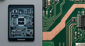
The IPC DFM overview describes rule profiles as a starting point, not a replacement for the fabricator’s own capability limits. Ask the intended supplier for its current rules before freezing geometry.
Fabrication checks before you release the PCB
| Check | What to provide or confirm | Typical hold if missing |
|---|---|---|
| Stackup and material | Layer order, finished thickness, copper weights, dielectric or impedance requirements | A supplier cannot quote or build the intended construction |
| Copper geometry | Trace/space, annular ring, copper-to-edge and plane clearances against chosen process | Features exceed the approved capability or need redesign |
| Drill and vias | Separate plated/non-plated drills, finished holes, aspect ratio, microvia or filled-via callouts | Hole intent or plating requirement is unclear |
| Mask and finish | Mask openings, dams, surface finish, edge contacts and controlled exclusions | Openings or finish choices conflict with assembly |
| Outputs and revision | Gerbers or ODB++/IPC-2581, drill map, fabrication drawing, revision and approved deviations | CAM package is incomplete or contradictory |
For a fine-pitch design, include the component pitch and actual fan-out requirements rather than asking the supplier to assume HDI. If a via-in-pad, sequential lamination, or specialized material is needed, specify it on the drawing and review the HDI versus standard PCB trade-offs separately. A bare-board rule cannot establish the final assembly yield by itself.
Assembly and test checks belong in the same handoff
For assembly, compare the BOM, polarity, footprints, assembly drawing, stencil and paste requirements, test access, and any programming or conformal-coating steps. Do not assume that a board that is fabricable is also easy to assemble. The same revision identifier should appear on the bare-board drawing, BOM, placement file, test instructions, and purchase order. Record any engineering change before the supplier releases production.
- Verify that every BOM line has an approved manufacturer part number or an explicit substitution rule.
- Confirm component-to-edge and component-to-component clearances using the actual enclosure and assembly process.
- Identify test points, programming access, and acceptance criteria before tooling is made.
- For a supplier question, respond with a controlled revision or signed deviation rather than a verbal instruction.
When should you run a DFM review?
Run a preliminary review once the architecture and key components are stable, then repeat it on the exact files intended for quotation and again after any material design revision. Early review is particularly valuable when the design depends on a narrow capability, such as fine-pitch BGA escape, high aspect-ratio holes, controlled impedance, or unusual materials. The final approval must use the same revision that is released to production.
What should a usable supplier DFM report show?
A useful report identifies the part and revision, rule or capability involved, affected location, severity, proposed disposition, owner, and approval status. The supplier should distinguish hard manufacturing limits from cost or yield suggestions. If the review reports no issues, retain the reviewed file set and date so the production build can be traced back to the approved baseline. QueenEMS can review a submitted manufacturing package and discuss questions, but this page does not promise a fixed response time, fee, or yield improvement; those terms must be confirmed for the specific order.
FAQ
Does passing DRC mean the PCB is ready to manufacture? No. DRC only checks the rules configured in the layout tool; stackup, CAM outputs, assembly, testing, and supplier capability still need review.
Can DFM guarantee zero production delay? No. It helps identify avoidable conflicts before release, but procurement, materials, process variation, and later engineering changes can still affect schedule.
What files should I send? Send the exact released fabrication files, drawings, stackup, drill data, BOM and assembly files relevant to the requested scope, all carrying a common revision. See IPC’s file-handoff guidance for additional context.
Upload your files today · Free DFM check before production · Ship worldwide
Get your PCB prototypes in as fast as 24 hours. We handle FR4, Rogers, and hybrid boards up to 40 layers in volume production, with advanced builds subject to engineering review — free prototypes for 2–4 layer FR-4 boards, no minimum order.
Just upload your Gerber + BOM — we source every part, assemble, and inspect (AOI + X‑Ray) so you don't have to chase suppliers. Boards ship in as fast as 24 hours.