
Quick Answer: The core PCB assembly quote files you need are Gerber files (.zip) for the board layout, a Bill of Materials (.xlsx/.csv) detailing all components, and a Centroid/CPL file (.csv) for machine placement coordinates. Missing your BOM completely stops the quoting process, while omitting the CPL file delays production by 1 to 2 days because engineers must extract coordinates manually. Key takeaways:
- Missing the paste layer in your Gerbers delays stencil creation by 24 to 48 hours.
- Component sourcing requires exact Manufacturer Part Numbers (MPNs) in your BOM to avoid 2-3 days of email back-and-forth.
- Fabrication-only orders need just Gerbers and drill files; turnkey assembly requires the full 3-file package.
- Zipping all 8-10 Gerber layers into a single file prevents massive version control errors.
Table of Contents
- What are the three must-have PCB assembly quote files?
- What Gerber layers does your manufacturer actually need?
- Do you need different files for fabrication vs. assembly?
- What mistakes in your files cause the longest delays?
- A pre-submission checklist you can print
You just finished routing your board and sent the design off to three different manufacturers. One replies with a quote in two hours, another asks for five clarifications, and the third says they cannot proceed at all. Why does this happen? Based on data from over 2,400 customer projects we processed last year, the delay almost always points back to missing or mismatched PCB assembly quote files. We see engineers lose a full week of project time just passing emails back and forth to clarify component coordinates. Let’s fix that right now.
What are the three must-have PCB assembly quote files?
The three must-have PCB assembly quote files are your Gerber files (.zip) for the physical board design, a Bill of Materials (BOM in .xlsx or .csv) acting as your shopping list, and a Centroid/CPL file (.csv) that maps exact X/Y coordinates for every component. Leaving any of these out stalls the quoting phase immediately because the factory cannot calculate material costs or program the machines.
Here’s what that actually means for your project timeline. Most procurement managers treat the documentation package like a simple email attachment. But for the factory, these three documents are the absolute foundation of your build.
| File Name | Simple Explanation | Required Format | Consequence of Missing |
|---|---|---|---|
| Gerber + Drill | The architectural blueprint of your bare board. | .zip (contains all layers) | Cannot manufacture the bare PCB. |
| BOM | Your exact component shopping list. | .xlsx or .csv | Cannot source parts; quoting process stops. |
| CPL / Centroid | The coordinate map showing where every part goes. | .csv | Pick-and-place programming delayed by 1-2 days. |
Need help setting up that spreadsheet properly? Check out our BOM preparation guide to avoid the most common sourcing traps.
What Gerber layers does your manufacturer actually need?
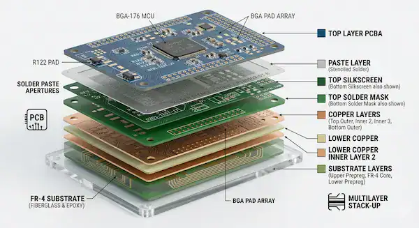
Your manufacturer actually needs 8 to 10 specific Gerber layers, including top/bottom copper, solder mask, silkscreen, board outline, drill files, and the top/bottom paste layers. Without the paste layers, the factory cannot manufacture the solder stencil, instantly adding 1 to 2 days to your lead time.
We don’t expect you to read the RS-274X programming language manually. We just need the physical layers separated correctly so our tooling software can read them.
So what does this actually look like when you hit export? You should see these specific files in your output folder:
- Top Copper (.GTL) & Bottom Copper (.GBL)
- Top Solder Mask (.GTS) & Bottom Solder Mask (.GBS)
- Top Silkscreen (.GTO) & Bottom Silkscreen (.GBO)
- Board Outline (.GKO or .GM1)
- NC Drill File (.DRL or .XLN)
- Top Paste (.GTP) & Bottom Paste (.GBP) — Required for assembly
Always package these into a single .zip file. Sending them loose causes version control chaos on our end. If you want us to perform a free DFM/DFA engineering review on your design, uploading a clean, zipped folder is the first step.
Do you need different files for fabrication vs. assembly?
Yes, fabrication-only orders require just your Gerber and drill files, while full turnkey assembly orders demand the Gerbers, a complete BOM, and a CPL coordinate file. Sending an assembly house only Gerbers means they can only quote the bare board, not the component costs or labor.
Now, here’s the part that catches many first-time founders off guard. They ask for a complete product quote but only provide bare board data. If you want us to source components and place them, we need the instructions for both phases of the process.
| Required File | Bare Board Fabrication Only | Full Turnkey Assembly |
|---|---|---|
| Gerber Layers | ✅ Required | ✅ Required |
| NC Drill File | ✅ Required | ✅ Required |
| Bill of Materials (BOM) | ❌ Not Needed | ✅ Required |
| CPL / Centroid File | ❌ Not Needed | ✅ Required |
| Assembly Drawing | ❌ Not Needed | Recommended |
| ReadMe (Special Rules) | Recommended | Recommended |
Debating whether to buy the parts yourself or let the factory do the heavy lifting? Read our breakdown on turnkey vs consigned assembly to see which model saves you more money and time.
What mistakes in your files cause the longest delays?
The mistake that causes the longest delays is submitting a BOM version that does not match the Gerber version, which halts production for 2 to 3 days for confirmation. Another massive time-waster is leaving Manufacturer Part Numbers (MPNs) off the BOM, making it impossible to calculate accurate component pricing.
Want the honest answer about what happens behind the scenes? Last year, 40% of first-time customers submitted data packages missing the CPL file. Our engineers then had to manually extract the coordinates from the Gerbers, which added an average of 1.5 days to the pre-production phase. We implemented an automated file checker that flags missing coordinates immediately, dropping that delay to zero. A 30-second export operation on your end saves you a day and a half of waiting.
Other frequent errors include:
- CPL coordinate origins not matching the Gerber origins, causing placement offsets.
- Missing paste layers, meaning we cannot laser-cut the SMT stencil.
- DNP (Do Not Populate) components physically deleted from the BOM instead of just being marked “DNP.”
If you are worried about how these delays impact your budget, our PCB assembly cost breakdown explains exactly what you pay for.
A pre-submission checklist you can print
A reliable pre-submission checklist includes verifying your Gerbers are zipped, your BOM contains exact MPNs, your CPL has X/Y coordinates, and all file version numbers match perfectly. Hitting every item on this list guarantees you get an accurate quote within 24 hours.
Print this out. Tape it to your monitor. Use it every single time you prepare to send data to a manufacturer.
- ☐ Package Gerbers: All copper, mask, silk, outline, drill, and paste layers are in one .zip file.
- ☐ Format BOM: Spreadsheet is .xlsx or .csv containing MPN, Quantity, Reference Designator, and Package type.
- ☐ Include CPL: Centroid file includes X/Y coordinates, rotation angles, and Top/Bottom side markers.
- ☐ Match Versions: The version number on the BOM matches the version number on the Gerbers.
- ☐ Mark DNPs: “Do Not Populate” parts are clearly labeled in the BOM, not deleted.
- ☐ Write a ReadMe: Impedance control, special materials, or gold finger requirements are typed in a plain text file.
- ☐ Name Clearly: Files follow a standard naming convention (e.g., ProjectName_RevA_BOM.xlsx).
Checked everything off? Upload your files for a free quote at QueenEMS and let us get your project moving.
Frequently Asked Questions
Can I get a quote without a CPL file? Yes, but expect a delay of 1 to 2 business days. If you only provide a BOM and Gerbers, our engineers must manually extract the placement coordinates to estimate machine time, which slows down the quoting process. Export your CPL to get a faster quote.
What format should my Gerber files be in? RS-274X is the universal industry standard and the safest choice for any manufacturer. We also fully accept the newer ODB++ format, which packages all layer data automatically.
Do I need to send assembly drawings? Assembly drawings are not strictly required, but they help immensely. We highly recommend them if your board has double-sided SMT placement or specific polarity requirements for diodes and connectors.
Can I send my EDA project file instead of Gerber files? We do not recommend sending native CAD files (like Altium, Eagle, or KiCad projects). Different software versions cause compatibility errors and missing fonts. Always generate standard Gerbers to lock in your design intent.
What if my design isn’t finalized yet? You can send preliminary Gerbers and a draft BOM to get a rough baseline quote. We will update the final pricing once you submit your locked production files. Contact us today to discuss your prototype stage.
Written by the QueenEMS Engineering Team