
FR4 material for PCB fabrication is a flame-retardant, woven glass-reinforced epoxy laminate that serves as the insulating backbone of most circuit boards. You meticulously design a complex layout, but ignoring thermal and electrical limits causes catastrophic board delamination during assembly. This critical oversight destroys your prototyping timeline and drastically inflates your engineering budget. Fortunately, our comprehensive guide breaks down the essential FR4 material specifications so you can specify fabrication parameters with absolute confidence.
Contents
- What exactly is FR4 material in PCB design?
- What are the key electrical properties of FR4 material?
- How do thermal properties impact FR4 material?
- What are the IPC-4101 standards for FR4 material?
- How to choose standard vs high-Tg FR4 material?
- What is the best thickness for your FR4 material?
- How does FR4 material compare to Rogers and Polyimide?
- What are the major brand options for FR4 material?
- What are the main limitations of standard FR4 material?
- How do you make the final decision on FR4 material?
What exactly is FR4 material in PCB design?
It is a composite grade designation for glass-reinforced epoxy laminate material used globally. Understanding your FR4 material proves crucial because it physically supports and electrically isolates your intricate copper routing. The abbreviation stands for flame retardant, indicating full compliance with strict UL94V-0 fire safety standards. This highly specialized blend provides an exceptional balance of mechanical strength and manufacturing cost-efficiency.
How is the woven glass structured?
The interwoven fiberglass cloth provides immense structural rigidity to the bare circuit board. Here is the deal: This robust grid prevents physical warping under extreme assembly stress.
- High tensile strength properties
- Consistent dimensional stability
- Excellent moisture resistance
What role does the epoxy resin play?
The epoxy resin acts as a highly durable binder surrounding the woven fiberglass core. It ultimately dictates the thermal limitations and dielectric characteristics of the final laminate stack-up.
| Component | Primary Function | Manufacturing Benefit |
|---|---|---|
| Woven Glass | Structural integrity | Prevents mechanical warping |
| Epoxy Resin | Thermal binding | Determines glass transition |
| Flame Retardant | Fire safety | Ensures UL94V-0 compliance |
This material breakdown proves that varying the resin chemistry directly alters the board’s thermal endurance capabilities.
Key Takeaway: You must deeply understand these composite elements because the specific resin formulation completely dictates your board’s operational limits.
What are the key electrical properties of FR4 material?
They encompass the dielectric constant, dissipation factor, and volume resistivity of the core substrate. Every electronic engineer relies on standard FR4 material to maintain pristine signal integrity across basic digital circuits. However, fluctuating electrical parameters can severely distort high-speed communication lines during operation. You must meticulously evaluate these critical metrics to prevent catastrophic signal degradation before manufacturing begins.
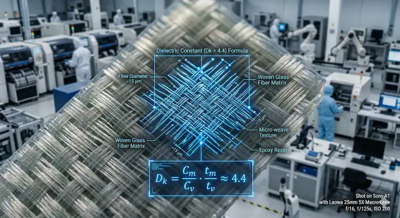
Why do Dk and Df matter?
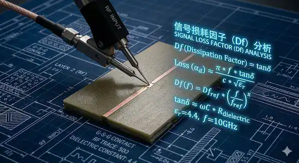
The dielectric constant determines how fast electrical signals travel through your copper traces. What is the real story? The dissipation factor measures how much signal energy continuously leaks as heat.
- Dk affects impedance calculations
- Df causes signal attenuation
- Both parameters vary with operating frequency
How does CTI prevent failures?
The Comparative Tracking Index evaluates the material’s resistance to surface electrical breakdown under voltage stress. Higher values prevent catastrophic short circuits in demanding high-voltage industrial applications.
| Electrical Property | Typical Value | Impact on Design |
|---|---|---|
| Dielectric Constant (Dk) | 4.2 to 4.8 | Impedance matching |
| Dissipation Factor (Df) | 0.015 to 0.02 | High-frequency loss |
| Volume Resistivity | >10^6 MΩ-cm | Leakage current prevention |
This electrical profile clearly illustrates why standard substrates struggle to support ultra-high-speed microwave transmissions cleanly.
This is the single most frequently asked question about FR4 material in engineering forums, and the answer is nuanced. Standard FR4 becomes problematic above 1–2 GHz because the loss tangent (Df ~0.02) causes significant signal attenuation at roughly 0.2 dB per inch at 5 GHz. However, the practical frequency limit depends entirely on your trace length and acceptable loss budget. For 2.4 GHz WiFi with short antenna traces under 2 inches, standard FR4 works perfectly fine and is used in millions of consumer routers and IoT devices. For 5 GHz WiFi, you can still use FR4 if you keep high-frequency traces extremely short (under 1 inch) and use a thinner laminate (0.8mm) to reduce dielectric path length. The critical breakpoint is typically around 3–4 GHz for traces longer than 3 inches, where insertion loss exceeds most designers’ budgets. Above 6 GHz, or for any trace longer than 5 inches at frequencies above 2 GHz, you should seriously evaluate low-loss FR4 variants like Isola FR408 (Df = 0.01) or switch to Rogers materials entirely. The key takeaway: frequency alone does not disqualify FR4. It is the combination of frequency, trace length, and your loss tolerance that determines whether FR4 is acceptable.
Key Takeaway: Always calculate your controlled impedance traces using the exact dielectric values provided by your specific laminate manufacturer.
How do thermal properties impact FR4 material?
Thermal properties dictate how much heat the laminate withstands before physically degrading or expanding excessively. When your FR4 material undergoes wave soldering, extreme temperatures aggressively test its structural limits. Exceeding these thermal thresholds rapidly causes delamination and irreversible copper pad lifting. You must align your material choice perfectly with your specific assembly temperature profiles.
Why is the Tg rating critical?
The Glass Transition Temperature marks exactly where the rigid board becomes soft and pliable. Picture this: Crossing this invisible threshold drastically increases the risk of catastrophic mechanical failure.
- Dictates maximum operating temperature
- Influences assembly thermal profiling
- Prevents resin matrix softening
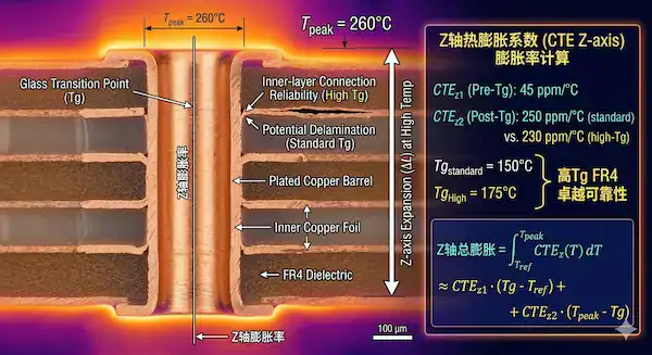
How does CTE affect your vias?
The Coefficient of Thermal Expansion measures how much the board expands vertically when heated. High Z-axis expansion physically tears plated through-holes apart during intense reflow soldering cycles.
| Thermal Metric | Definition | Manufacturing Risk |
|---|---|---|
| Tg (Glass Transition) | Softening point | Structural weakening |
| Td (Decomposition) | Chemical breakdown | Permanent delamination |
| CTE (Z-axis) | Vertical expansion | Broken via barrels |
This thermal data confirms that excessive Z-axis expansion remains the leading cause of hidden via failures during assembly.
Lead-free reflow typically reaches peak temperatures of 245–260°C, which is well above standard FR4’s Tg of 130°C. However, exceeding Tg does not instantly destroy the board. It means the resin softens and Z-axis expansion accelerates dramatically. For simple 2-layer or 4-layer boards with standard via sizes (0.3mm drill or larger), standard Tg FR4 can survive 1–2 lead-free reflow cycles without reliability issues. The danger emerges with multiple reflow passes (double-sided assembly requires two passes), high layer counts (8+ layers), or small vias (under 0.2mm drill) where the cumulative Z-axis expansion during each thermal cycle progressively fatigues the copper barrel plating. The industry consensus is: use standard Tg for single-sided assembly on boards with 4 or fewer layers. Upgrade to mid-Tg (150°C+) for double-sided assembly. Mandate high-Tg (170°C+) for any board over 8 layers, any board requiring 3+ thermal cycles, or any board with microvias. The cost premium for high-Tg material is typically only 5–10% of total board cost, making it cheap insurance for complex designs.
Key Takeaway: You must specify a laminate featuring a sufficiently high transition temperature to survive multiple lead-free reflow cycles safely.
What are the IPC-4101 standards for FR4 material?
IPC-4101 provides the global regulatory framework that standardizes base materials for rigid printed boards. Identifying the correct FR4 material slash sheet guarantees your factory uses the exact chemical formulation required. Ignoring these specifications often leads to unauthorized, cheap material substitutions by budget-focused vendors. You must mandate specific slash sheets to maintain strict engineering quality control.
How do you decode slash sheets?
Slash sheets define specific performance tiers based on unique resin systems and thermal reinforcements. Now let’s get down to business: They replace ambiguous brand names with highly verifiable engineering parameters.
- /21 specifies standard epoxy
- /24 includes UV blocking compounds
- /26 offers significantly higher Tg
Which sheet fits your project?
Selecting the correct designation ensures total compliance with international lead-free assembly protocols. It aligns your complex engineering intent perfectly with the physical fabrication reality on the factory floor.
| IPC-4101 Sheet | Tg Range (°C) | Primary Application |
|---|---|---|
| /21 | 100 – 130 | Standard consumer goods |
| /24 | 150 – 170 | Mid-tier industrial boards |
| /26 | 170 – 200 | High-reliability environments |
This classification matrix proves that relying solely on generic trade names remains dangerous for high-reliability circuit design.
Key Takeaway: Explicitly list your required slash sheet in your fabrication notes to legally prevent factories from substituting cheaper alternatives.
How to choose standard vs high-Tg FR4 material?
You choose based on the thermal stress of your operating environment and overall assembly complexity. Standard FR4 material works flawlessly for simple consumer electronics that run relatively cool continuously. However, dense multi-layer designs subjected to multiple high-temperature soldering cycles absolutely demand advanced thermal resilience. You must analyze your complete thermal budget before finalizing the printed circuit stack-up.
When is standard 130C acceptable?
Standard laminates remain highly cost-effective for single or double-sided bare boards without advanced components. Believe it or not: They are perfectly adequate for simple, low-power applications lacking severe thermal demands.
- Excellent for fast prototyping
- Lowest raw material cost available
- Easy mechanical drilling operations
Why upgrade to 170C high-Tg?
Advanced materials withstand over 170°C natively, making them essential for thick, multi-layer architectures. They aggressively prevent severe vertical expansion that typically fractures internal micro-vias during manufacturing.
| Tg Classification | Temp Range | Best Used For |
|---|---|---|
| Standard Tg | 130°C – 140°C | 2-4 layer standard boards |
| Mid-Tg | 150°C – 160°C | 6-8 layer lead-free assembly |
| High-Tg | >170°C | 10+ layers, severe environments |
This thermal comparison illustrates that investing in higher transition temperatures exponentially increases the survivability of dense multi-layer vias.
Key Takeaway: Always upgrade to an advanced laminate if your design features more than eight layers or operates in harsh industrial climates.
What is the best thickness for your FR4 material?
The best thickness depends entirely on your layer count, mechanical clearance, and strict impedance requirements. Specifying the correct FR4 material thickness guarantees physical rigidity and proper edge connector mating. Thin boards risk severe warping continuously, while overly thick boards complicate through-hole component soldering processes. You must balance mechanical stability perfectly with your specific electronic packaging constraints.
When should you use ultra-thin boards?
Profiles measuring 0.4mm to 0.8mm perform perfectly for compact wearables and lightweight aerospace sensors. Truth be told: They save critical space but require extreme care during automated pick-and-place assembly.
- Ideal for tight device enclosures
- Lower overall product weight
- Requires specific handling pallets
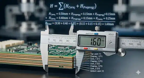
Why is 1.6mm the global standard?
The 1.6mm profile provides the absolute perfect balance of mechanical strength and manufacturing ease. It is universally accepted by nearly all standard edge connectors and factory assembly fixtures worldwide.
| Board Thickness | Common Layer Count | Typical Application |
|---|---|---|
| 0.4mm – 0.8mm | 2 to 4 Layers | Wearables, smartcards |
| 1.6mm | 2 to 6 Layers | Standard computing, IoT |
| 2.4mm – 3.2mm | 8 to 16+ Layers | Heavy backplanes, servers |
This thickness hierarchy shows that increasing layer counts fundamentally requires thicker substrates to accommodate complex internal routing safely.
Key Takeaway: Verify your intended enclosure clearances and edge connector specifications before locking in your final dielectric thickness. If unsure, upload your design files, and our engineers will recommend the best stack-up for free via our rapid PCB prototyping service.
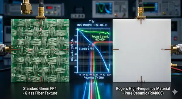
How does FR4 material compare to Rogers and Polyimide?
It offers vastly superior cost-efficiency but lacks the high-frequency performance of Rogers and Polyimide’s dynamic flexibility. While FR4 material dominates general electronics, specialized applications quickly expose its fundamental physical limitations. Designers constantly debate whether absorbing the premium cost of exotic materials truly improves overall signal integrity. You must weigh raw performance advantages heavily against your strict manufacturing budget.
What is the high-frequency Rogers advantage?
Rogers materials provide incredibly stable dielectric constants and near-zero signal loss at microwave frequencies. You might be wondering: Is the drastic price increase truly justified for commercial products?
- Essential for radar and 5G
- Extremely low moisture absorption
- Highly stable Dk values
Where does flexible Polyimide excel?
Polyimide completely replaces rigid boards in applications requiring dynamic bending and continuous physical movement. It handles extreme heat exceptionally well but requires highly specialized, expensive fabrication techniques.
| Material Type | Primary Advantage | Main Limitation |
|---|---|---|
| Standard FR-4 | Highly cost-effective | High signal attenuation |
| Rogers (PTFE) | Superior RF performance | Extremely expensive |
| Polyimide (PI) | Dynamic flexibility | Difficult to assemble |
This material triad demonstrates that pushing into the gigahertz spectrum or requiring dynamic motion demands abandoning standard epoxy resins.
Hybrid stackups combining Rogers and FR4 are a well-proven, cost-effective solution widely used in commercial RF products. The typical approach places Rogers material (such as RO4350B) as the top two layers where your RF traces and antenna structures reside, while using standard FR4 for the remaining inner layers that carry digital signals and power planes. This can reduce material costs by 40–60% compared to an all-Rogers stackup. However, hybrid constructions introduce two engineering challenges you must address. First, the CTE mismatch between Rogers and FR4 creates internal stress during thermal cycling, which can cause delamination at the material interface over time. Specifying a mid-Tg or high-Tg FR4 (150°C+) for the FR4 layers minimizes this risk. Second, the different Dk values between the Rogers layers (Dk ~3.48) and FR4 layers (Dk ~4.3) mean you must calculate impedance separately for each layer pair rather than using a single Dk value for the entire stackup. Most PCB manufacturers experienced in RF fabrication can handle hybrid lamination routinely. Confirm with your fabricator before committing to a hybrid design, and request their specific stackup recommendation with exact prepreg bonding materials.
Key Takeaway: Only switch to premium laminates like Rogers when your RF signal attenuation calculations prove that standard epoxy will fail.
What are the major brand options for FR4 material?
Shengyi, Isola, ITEQ, and Nanya represent the leading global manufacturers providing highly reliable substrate laminates. Selecting a specific FR4 material brand ensures predictable electrical performance across massive production runs. Generic, unbranded laminates often exhibit wild parameter variations that ruin sensitive impedance calculations unexpectedly. You must specify a trusted brand model to guarantee consistent manufacturing yields continuously.
How do Shengyi and Isola compare?
Shengyi excels in providing rock-solid, highly cost-effective laminates for high-volume commercial manufacturing worldwide. Let’s dive in: Isola focuses heavily on premium, high-speed digital materials for advanced computing architectures.
- Shengyi S1000: Ultimate reliable workhorse
- Isola FR408: High-speed digital champion
- Both offer massive global availability
What about ITEQ and Nanya models?
ITEQ provides exceptional thermal options performing brilliantly in severe automotive and industrial environments daily. Nanya dominates the memory and consumer electronics sector delivering highly stable, medium-tier solutions consistently.
| Brand & Model | Tg (°C) | Dk (at 1GHz) | Best Use Case |
|---|---|---|---|
| Shengyi S1000-2 | 170 | 4.3 | High-Tg general use |
| Isola FR408 | 180 | 3.7 | High-speed digital |
| ITEQ IT-180A | 175 | 4.4 | Automotive electronics |
| Nanya NP-155F | 150 | 4.3 | Mid-tier consumer goods |
This brand matrix clarifies that optimizing for high-speed signal integrity requires transitioning away from standard workhorse laminates immediately.
Key Takeaway: Partner closely with your fabrication house selecting a specific brand model matching your precise impedance and thermal requirements.
What are the main limitations of standard FR4 material?
It suffers from significant signal attenuation at high frequencies while exhibiting unpredictable dielectric constant variations. Pushing standard FR4 material beyond 3 GHz results in corrupted data streams and massive power losses. Engineers mistakenly stretch standard laminate limits attempting to save money, resulting in disastrous field failures. You must recognize these hard physical boundaries thoroughly before finalizing your high-speed layouts.
Why does it struggle with microwaves?
The epoxy resin matrix acts remarkably like a sponge, absorbing high-frequency signal energy instantly. This is where it gets interesting: The dissipation factor climbs aggressively as operating frequencies increase continuously.
- Unacceptable signal insertion loss
- Severely degraded eye diagrams
- Increased overall bit error rates
Is the dielectric constant truly stable?
Unlike advanced PTFE materials, standard epoxy laminates experience notable parameter shifts across different temperatures. This inherent chemical instability makes precise, long-distance impedance matching nearly impossible for RF designers.
| Limitation | Root Cause | Engineering Consequence |
|---|---|---|
| High Freq Loss | High dissipation factor (Df) | Shorter viable trace lengths |
| Dk Instability | Resin chemistry variations | Impedance mismatching errors |
| Heat Retention | Low thermal conductivity | Component overheating risks |
This performance breakdown proves that standard laminates represent a severe bottleneck for next-generation telecommunications and radar systems.
Impedance variation between FR4 batches is one of the most frustrating real-world issues designers face, and it stems from FR4’s inherent Dk tolerance of ±10%. Unlike specialized laminates (Rogers RO4350B has ±1.5% Dk tolerance), standard FR4’s dielectric constant varies between 4.2 and 4.8 depending on the glass weave style, resin content ratio, and curing conditions. These factors change between manufacturers and even between production lots from the same supplier. For designs requiring tight impedance control (±5%), you must take three specific actions. First, specify a named laminate model (such as Shengyi S1000-2 or ITEQ IT-180A) rather than generic “FR4” in your fabrication notes, because each model has a documented Dk with tighter tolerances. Second, request impedance test coupons on your production panel so the fabricator can verify impedance before shipping. Third, design your stackup with the manufacturer’s exact Dk value from their datasheet rather than using the generic 4.5 assumption that most impedance calculators default to. These three steps can reduce your batch-to-batch impedance variation from ±10% to ±5%.
Key Takeaway: If your design features multi-gigabit data links, transition to hybrid stack-ups or dedicated high-speed laminates immediately.
How do you make the final decision on FR4 material?
You make the decision evaluating your operating frequency, extreme thermal environment, layer count, and overall budget. Choosing the correct FR4 material requires a strategic balancing act between required performance and manufacturing costs. Over-specifying materials wastes immense amounts of money, while under-specifying guarantees catastrophic functional failures. You must utilize a structured decision matrix validating your final laminate selection confidently.
How do you weigh frequency and temperature?
If your signals exceed 3 GHz, consider advanced RF laminates or custom hybrid stack-ups immediately. What is the real story? If your assembly requires multiple lead-free reflows, premium laminates remain mandatory regardless of frequency.
- Define maximum peak operating frequency
- Calculate anticipated thermal exposure cycles
- Assess intense environmental physical stresses
How do you balance layers and cost?
High layer counts exponentially increase vertical thermal stress, demanding premium, dimensionally stable resin systems. Upgrading to a specialized laminate escalates bare board costs significantly, impacting your total bottom line.
| Decision Factor | Low Complexity | High Complexity | Recommended Action |
|---|---|---|---|
| Signal Speed | < 1 GHz | > 3 GHz | Switch to Rogers/Isola |
| Thermal Cycles | Single Reflow | Multiple Reflows | Mandate High-Tg |
| Layer Count | 2 to 4 Layers | 10+ Layers | Use premium brands |
This decision framework systematically eliminates costly guesswork, ensuring your material choice aligns perfectly with physical constraints.
Key Takeaway: Run your design through this strict four-pillar evaluation matrix before issuing your final bill of materials to the factory.
Conclusion
This definitive guide resolved the complex challenges surrounding laminate selection, proving that precise material specification is crucial for manufacturing success. We deliver comprehensive engineering reviews, rigorous DFM checks, and premium fabrication ensuring your designs perform flawlessly in the real world. QueenEMS remains passionately committed to elevating your hardware reliability through uncompromised material science and transparent manufacturing excellence. To secure your production timeline with expert engineering guidance, contact us today and experience true factory-direct precision.
FAQ
Q1: What is the best way to handle impedance control on standard substrates? You must closely collaborate with your fabrication factory to get their specific parameters for their stocked materials. Generic calculations often fail because actual characteristics vary wildly between different laminate brands and glass weave styles.
Q2: Can I use standard 130°C laminates for lead-free soldering? No. Lead-free reflow profiles generate immense heat that easily exceeds the thermal limits of standard 130°C materials. You must specify at least a medium-level laminate to prevent internal delamination during assembly.
Q3: How do I know if my design requires a Rogers upgrade? You should run signal integrity simulations on your critical RF or high-speed digital traces. If the insertion loss on standard epoxy exceeds your allowable power budget, you must upgrade to Rogers.
Q4: What’s the best thickness for a dense 8-layer circuit board? You should target a standard 1.6mm or 2.0mm thickness to provide adequate physical rigidity for eight internal layers. Thinner profiles for 8-layer boards require expensive, ultra-thin prepregs that complicate manufacturing.
Q5: Can I mix Rogers and standard laminates in one board? Yes. A hybrid stack-up places expensive Rogers material on the critical outer high-frequency layers while using cheap epoxy for internal power planes. This highly efficient strategy maximizes signal performance while drastically reducing overall fabrication costs.