

High Reliability PCB Assembly for Battery & EV Electronics
One soldering defect can mean safety risks, costly recalls, or certification failure.
Your power electronics demand precision, consistency, and full traceability — not just competitive pricing.
The Real Challenges in Battery & EV PCB Assembly
These aren't theoretical concerns — they're the daily realities that separate reliable suppliers from risky ones.
High-Power Soldering Risks
High current and voltage make soldering integrity critical. Microcracks invisible at inspection can fail under thermal cycling or vibration.
BMS Batch Consistency
Battery Management Systems require identical performance across thousands of units. Process drift or component variation creates safety liabilities.
Insufficient Testing Coverage
Assembly-level testing alone misses functional failures that only appear under load, temperature stress, or real operating conditions.
Certification Pressure
CE, UL, and automotive standards demand documented process control and material traceability. Last-minute compliance gaps delay market entry.
Component Substitution Risks
Unauthorized part swaps during supply chain disruptions can invalidate certifications or cause field failures months after shipment.
Does this sound familiar? Let's discuss how to address these challenges systematically.
Review Your Project RequirementsWhy Battery & EV PCB Assembly Risks Far Exceed Consumer Electronics
The stakes are fundamentally different. While consumer electronics fail gracefully, power electronics fail catastrophically.
Failure = Inconvenience
- Low voltage/current operation reduces thermal and electrical stress
- Short product lifecycles mean failures occur after replacement cycles
- Field failures typically result in returns or warranty claims
- Testing focuses on basic functionality rather than long-term reliability
- Component tolerances have wider acceptable ranges
Failure = Disaster
- High power density creates extreme thermal and electrical demands on every joint
- 10+ year operational life requires zero degradation in safety-critical systems
- Field failures trigger recalls, regulatory action, and brand damage
- Must pass rigorous thermal cycling, vibration, and load testing before certification
- Component specifications must meet automotive-grade or industrial standards
Your assembly partner must understand these distinctions at every process step.
Explore Our ApproachCommon Failure Scenarios in Battery & EV Production
These are actual patterns observed across the industry — not theoretical risks. Each represents preventable issues that escaped quality control.
Solder Joint Microcracking
High-current power modules passed initial visual and AOI inspection but developed hairline cracks during thermal cycling.
Result: Intermittent failures appeared 6 months after deployment, requiring field replacements and warranty claims exceeding original production costs.
Unauthorized Component Substitution
Factory substituted non-automotive grade capacitors during shortage without engineering approval or documentation.
Result: Certification invalidated upon audit. Entire production batch quarantined pending rework with correct components, delaying market launch by 4 months.
Inadequate Functional Testing
BMS boards tested only at room temperature without load simulation. Thermal management failures only manifested under continuous high-current operation.
Result: Field failures during customer stress testing revealed design-for-manufacturing issues that should have been caught earlier, triggering redesign delays.
Prevention requires engineering discipline, not just inspection after the fact.
See How We Prevent These IssuesWhat Battery & EV Customers Actually Care About
These aren't negotiable preferences — they're fundamental requirements that separate viable suppliers from liabilities.
Batch Consistency
Every unit must perform identically under stress. Process variation that's acceptable in consumer products creates failure modes in power systems.
Thermal & Soldering Control
High-current joints require precise thermal profiles and verification. Standard SMT processes alone are insufficient for power electronics.
Comprehensive Testing
Beyond AOI and basic continuity — functional testing under thermal and electrical load conditions that simulate real deployment.
Full Traceability
Every component batch, process parameter, and test result must be documented and retrievable for certification audits and failure analysis.
Transparent Communication
Engineering questions need engineering answers, not sales deflection. Issues must be escalated immediately, not hidden until they become crises.
Ready to work with a partner who prioritizes what matters?
Start the ConversationHow We Address Battery & EV PCBA Challenges
These aren't marketing promises — they're engineered workflows built to prevent the failures outlined above.
Engineering Review
DFM analysis catches high-current trace issues, thermal management risks, and component placement problems before production begins, not after failures occur.
Controlled Sourcing
No unauthorized substitutions. Every component change requires written approval with full documentation and traceability back to original specifications.
Process Stability
Thermal profiles validated for power components. Batch-to-batch consistency monitored through statistical process control, not just visual checks.
Testing Strategy
Multi-layer verification: AOI, X-ray for power joints, functional testing under load. Defects caught before shipment, not in the field.
Each step is designed to prevent specific failure modes documented in the industry.
Review Our Process DocumentationDFM & DFA: Catching Battery PCBA Risks Before Production
Design for Manufacturing and Assembly analysis identifies high-current trace problems, thermal stress points, and assembly risks when changes are still cheap to make.
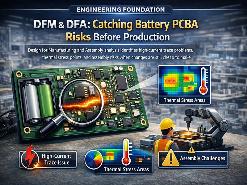
High-Current Trace Analysis
We verify trace widths against current requirements, identify potential voltage drop issues, and flag thermal hotspots before copper is etched.
Pad & Joint Design Review
Power device pads require specific thermal relief patterns and solder volumes. Standard consumer electronics pad designs fail under high-current stress.
Assembly Risk Identification
Large power components create shadowing during reflow. We flag placement issues that lead to tombstoning, insufficient solder joints, or thermal imbalance.
BOM Risk Assessment
Component obsolescence, long lead times, and single-source dependencies get flagged early, allowing procurement strategy adjustments before production commits.
Engineering review isn't optional for power electronics — it's how you avoid expensive redesigns.
Submit Your Design for ReviewBMS & Power Electronics Soldering Control
High-current joints fail differently than consumer electronics. Our process control addresses the specific failure modes unique to power applications.
High-Power Device Soldering
MOSFETs, IGBTs, and high-current connectors require validated thermal profiles. We monitor actual joint temperatures, not just oven settings, to ensure consistent intermetallic formation.
Mixed Technology Assembly
SMT and through-hole components on BMS boards require coordinated thermal management. Our dual-process control prevents damage to sensitive ICs while ensuring robust power connections.
AOI + X-ray Verification
Automated Optical Inspection catches surface issues. X-ray inspection reveals hidden voids and cracks in high-current joints that visual inspection misses — critical for power electronics reliability.
Process control determines whether your boards last 10 years or fail in 6 months.
Learn About Our Quality SystemsComponent Sourcing & Substitution Control for Battery Electronics
Unauthorized part changes invalidate certifications and create field failures. Our sourcing process eliminates substitution risks that plague the industry.
Zero Unauthorized Substitution
No component changes without written engineering approval. Period. Not "equivalent" parts, not "same specification" alternatives — your approved BOM is what gets assembled.
Documented Approval Process
When supply chain issues require alternatives, we document the proposed change, provide full datasheets and comparison data, and wait for your written authorization before proceeding.
Batch Traceability
Every component batch is logged with date codes, lot numbers, and supplier information. If a field issue emerges, you can trace it back to the specific component batch used in affected units.
Component integrity isn't negotiable when certifications and safety are at stake.
Discuss Your Component RequirementsBattery & EV Electronics Testing Strategy
Assembly verification alone is insufficient for power electronics. Our multi-layer testing catches functional failures before they reach your facility — or worse, your customers.
AOI Inspection
Automated Optical Inspection verifies component presence, orientation, and solder appearance on every board. Catches placement errors and obvious solder defects.
X-ray Analysis
X-ray inspection on high-current joints reveals voids, cracks, and insufficient solder that AOI cannot see. Critical for power device reliability verification.
Functional Testing
Custom test fixtures verify actual circuit operation under load conditions. Not just continuity — we confirm the board performs its intended function before shipment.
Burn-In & Stress Testing
For critical applications, thermal cycling and extended operation under load reveals infant mortality failures before boards leave our facility instead of failing in the field.
Testing strategy defines the difference between finding problems early or managing field failures later.
Design Your Testing ProtocolProduction Models for Battery & EV Customers
Whether you're validating prototypes or scaling to mid-volume production, our approach adapts to your development stage without compromising quality standards.
Development Phase Support
Engineering-intensive phase where designs evolve rapidly. We provide the same manufacturing discipline and documentation as production runs, preparing your design for scalability.
- DFM review on initial submissions catches issues before first build
- Quick-turn capabilities for iterative design validation cycles
- Full testing protocol development during prototype phase
- Engineering documentation for seamless production transition
- Component sourcing strategy established early
Production Deployment
Volume production with process controls that maintain consistency across batches. Ideal for market entry, specialty applications, and controlled scaling before mass production.
- Process validation and statistical control for batch consistency
- Flexible scheduling accommodates demand fluctuations
- Full traceability and documentation for certification compliance
- Scalable from hundreds to thousands of units per month
- Component inventory management reduces lead time variability
Your production requirements determine our approach, not arbitrary minimum order quantities.
Discuss Your Volume RequirementsWhy Battery & EV Customers Choose China PCBA—And How to Control the Risks
The advantages are real. So are the risks. Understanding both lets you capture the benefits while engineering around the failure modes.
The Advantages
Established supply chain for power electronics components, cost structure competitive for mid-volume production, flexible manufacturing capacity that scales with demand, and engineering resources available for complex assemblies.
The Real Risks
Inconsistent process discipline across suppliers, unauthorized component substitutions during shortages, inadequate testing leading to field failures, documentation gaps that complicate certification, and communication barriers during problem resolution.
Risk Mitigation Strategy
Documented engineering protocols prevent unauthorized changes, controlled sourcing with full traceability eliminates substitution risks, comprehensive testing catches failures before shipment, and direct engineering communication bypasses sales-layer filtering.
The location matters less than the process discipline and transparency.
Evaluate Our Quality SystemsOur Role in Battery & EV Projects: Manufacturing Partner, Not Contract Manufacturer
The distinction matters. Contract manufacturers execute orders. Manufacturing partners collaborate on solutions to prevent problems you didn't know existed.
Order Execution Model
- Sales team handles all communication, filters technical questions
- Engineering involvement only after problems emerge
- DFM review treated as formality, not genuine risk assessment
- Component substitutions decided internally without notification
- Testing limited to what's explicitly specified in PO
- Issues discovered after shipment become "customer's problem"
Collaborative Partnership
- Direct engineering communication from project initiation
- Proactive DFM analysis catches issues before they become problems
- Collaborative problem-solving when design or supply chain challenges arise
- Transparent component sourcing with documented approval process
- Testing strategy developed jointly based on application requirements
- Continuous improvement feedback from production to design
Your success determines our success — not just closing purchase orders.
Experience the DifferenceBattery & EV Applications We Support
Each application carries specific requirements for power density, thermal management, and reliability. Our process adapts to your use case.
BMS Control Boards
Battery Management Systems requiring precise voltage monitoring, cell balancing, and thermal management across pack lifecycles.
Battery Protection Modules
Overcurrent, overvoltage, and thermal protection circuits preventing catastrophic failures in lithium-ion battery applications.
EV Power Control Units
Motor controllers, inverters, and DC-DC converters managing high-voltage, high-current power conversion in electric vehicles.
Charging System Electronics
On-board chargers, DC fast charging controllers, and power factor correction circuits for battery charging infrastructure.
If your application involves battery power or EV electronics, we understand the specific challenges.
Discuss Your ApplicationLet's Review Your Battery or EV PCBA Project
If your project requires stable, traceable, and engineering-driven PCBA assembly, we should talk before problems emerge.
This conversation isn't a sales pitch — it's an engineering assessment of whether our capabilities match your requirements.
Response within 24 hours. Direct engineering contact, not sales filtering.
Tell Us About Your PCBA Project
Get a customized quote within 24 hours. Our team is ready to help you find the perfect solution for your needs
Email Us
[email protected]
Response within 12 hours
Call / WhatsApp
+86-0755-363091328
Mon - Sat, 9AM-6PM CST
Visit Our Factory
1-4/F Property Office Building, ZhengFeng North Road, Shenzhen, China. 518103